一、相机标定简介
相机标定指建立相机图像像素位置与场景点位置之间的关系,根据相机成像模型,由特征点在图像中坐标与世界坐标的对应关系,求解相机模型的参数。相机需要标定的模型参数包括内部参数和外部参数。
针孔相机成像原理其实就是利用投影将真实的三维世界坐标转换到二维的相机坐标上去,其模型示意图如下图所示: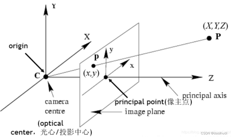
从图中我们可以看出,在世界坐标中的一条直线上的点在相机上只呈现出了一个点,其中发生了非常大的变化,同时也损失和很多重要的信息,这正是我们3D重建、目标检测与识别领域的重点和难点。实际中,镜头并非理想的透视成像,带有不同程度的畸变。理论上镜头的畸变包括径向畸变和切向畸变,切向畸变影响较小,通常只考虑径向畸变。
径向畸变:径向畸变主要由镜头径向曲率产生(光线在远离透镜中心的地方比靠近中心的地方更加弯曲)。导致真实成像点向内或向外偏离理想成像点。
枕形畸变:畸变像点相对于理想像点沿径向向外偏移,远离中心;
桶状畸变:径向畸点相对于理想点沿径向向中心靠拢。
数学公式表示:
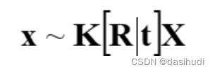
则有:

其中,X为相机中的坐标;|X为真实世界坐标;K为内参矩阵;**[R|t]为外参矩阵,K为内参矩阵,是相机内部参数组成的一个3*3的矩阵,其中,f代表焦距;s为畸变参数,(x0,y0)**x0=ay0为中心点坐标,a为纵横比例参数,我们可以默认设为1,所以x0=ay0。
[R|t]为外参矩阵,R是描述照相机方向的旋转矩阵,t是描述照相机中心位置的三维平移向量。
二、张友正黑白棋盘标定思想
张正友标定法利用黑白棋盘格标定板,在得到一张标定板的图像之后,用Harris角点检测算法得到每一个角点的像素坐标 (u,v) 。张正友标定法将世界坐标系固定于棋盘格上,则棋盘格上任一点的物理坐标W=0,由于标定板的世界坐标系是人为事先定义好的,标定板上每一个格子的大小是已知的,我们可以计算得到每一个角点在世界坐标系下的物理坐标(U,V,W=0) 。我们将利用这些信息:每一个角点的像素坐标 、每一个角点在世界坐标系下的物理坐标,来进行相机的标定,获得相机的内外参矩阵、畸变参数。
三、算法原理
31.模型
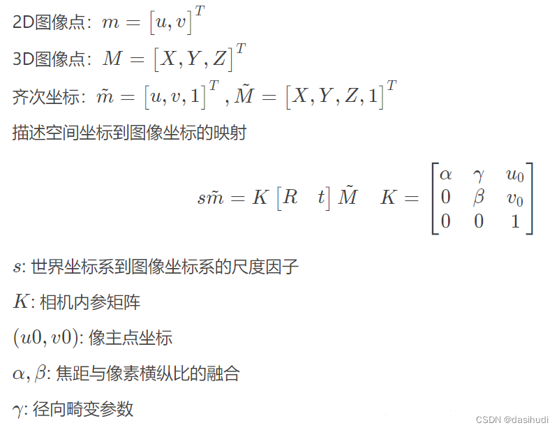
3.2 模型求解
-计算单应性矩阵
单应性:在计算机视觉中被定义为一个平面到另一个平面的投影映射。首先确定,图像平面与标定物棋盘格平面的单应性。
设棋盘格位于Z=0,定义旋转矩阵R的第i列为ri, 则有:

则空间到图像的映射可变为:

- 其中H 是描述Homographic矩阵,可通过最小二乘,从角点世界坐标到图像坐标的关系求解。
- 计算内参数矩阵
令H= [h1 h2 h3 ]

Homography有8个自由度,通过上述等式的矩阵运算,根据r1和r2正交,以及归一化的约束可以得到如下等式:
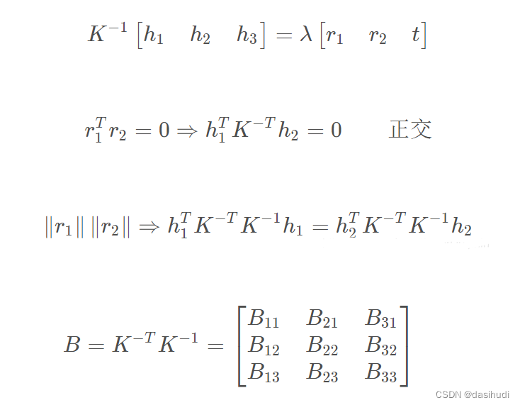
定义:
其中:

B时对称阵,其未知量可表示为6D向量b:

设H为第i列 中的hi
根据b的定义,可以推出如下公式:
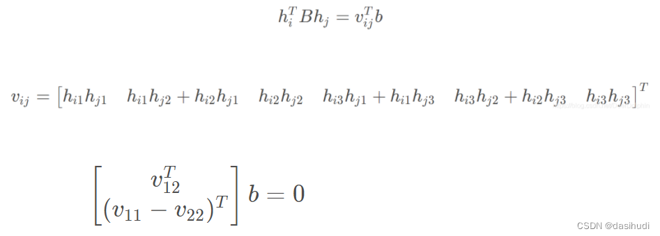
即可推导出:
内部参数可通过如下公式计算(cholesky分解):
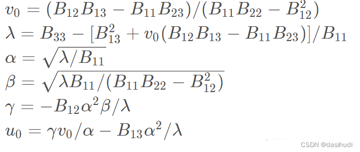
3.外部参数求解

4.极大似然估计
给定 n张棋盘格图像,每张图像有 m 个角点,最小化下述公式等同于极大似然估计:

上述非线性优化问题可以利用Levenberg-Marquardt 算法求解,需要初值K,Ri,ti|i=1…n
四、实验内容及过程
4.1 实验要求
1.打印一张棋盘格A4纸张(黑白间距已知),并贴在一个平板上
2.针对棋盘格拍摄若干张图片(一般10-20张)
3.在图片中检测特征点(Harris角点)
4.根据角点位置信息及图像中的坐标,求解Homographic矩阵
5.利用解析解估算方法计算出5个内部参数,以及6个外部参数
6.根据极大似然估计策略,设计优化目标并实现参数的refinement
4.2 实验数据及环境
1.实验数据
手机拍摄各个角度下打印的黑白棋盘格图片12张:
2.实验环境
win 10 ,64位,python3.6.5 ,OpenCV 4.2.0
4.3实现代码
# -*- coding: utf-8 -*-
import os
import numpy as np
import cv2
import glob
import re

def calib(inter_corner_shape, size_per_grid, img_dir, img_type):
    # criteria: only for subpix calibration, which is not used here.
    # criteria = (cv2.TERM_CRITERIA_EPS + cv2.TERM_CRITERIA_MAX_ITER, 30, 0.001)
    w, h = inter_corner_shape
    # cp_int: corner point in int form, save the coordinate of corner points in world sapce in 'int' form
    # like (0,0,0), (1,0,0), (2,0,0) ....,(10,7,0).
    cp_int = np.zeros((w * h, 3), np.float32)
    cp_int[:, :2] = np.mgrid[0:w, 0:h].T.reshape(-1, 2)
    # cp_world: corner point in world space, save the coordinate of corner points in world space.
    cp_world = cp_int * size_per_grid

    obj_points = []  # the points in world space
    img_points = []  # the points in image space (relevant to obj_points)
    images = glob.glob(img_dir + os.sep + '**.' + img_type)
    for fname in images:
        # print(re.sub("\D", "", fname))
        img = cv2.imread(fname)
        gray_img = cv2.cvtColor(img, cv2.COLOR_BGR2GRAY)
        # find the corners, cp_img: corner points in pixel space.
        ret, cp_img = cv2.findChessboardCorners(gray_img, (w, h), None)
        # if ret is True, save.
        if ret == True:
            # cv2.cornerSubPix(gray_img,cp_img,(11,11),(-1,-1),criteria)
            obj_points.append(cp_world)
            img_points.append(cp_img)
            # view the corners
            cv2.drawChessboardCorners(img, (w, h), cp_img, ret)
            cv2.imwrite('D:\\ComputerVision_code\\save_img\\' + re.sub("\D", "", fname) + '.jpg', img)
            # cv2.waitKey(1000)
    # cv2.destroyAllWindows()
    # calibrate the camera
    ret, mat_inter, coff_dis, v_rot, v_trans = cv2.calibrateCamera(obj_points, img_points, gray_img.shape[::-1], None,
                                                                   None)
    print(("ret:"), ret)
    print(("internal matrix:\n"), mat_inter)
    # in the form of (k_1,k_2,p_1,p_2,k_3)
    print(("distortion cofficients:\n"), coff_dis)
    print(("rotation vectors:\n"), v_rot)
    print(("translation vectors:\n"), v_trans)
    # calculate the error of reproject
    total_error = 0
    for i in range(len(obj_points)):
        img_points_repro, _ = cv2.projectPoints(obj_points[i], v_rot[i], v_trans[i], mat_inter, coff_dis)
        error = cv2.norm(img_points[i], img_points_repro, cv2.NORM_L2) / len(img_points_repro)
        total_error += error
    print(("Average Error of Reproject: "), total_error / len(obj_points))

    return mat_inter, coff_dis

def dedistortion(inter_corner_shape, img_dir, img_type, save_dir, mat_inter, coff_dis):
    w, h = inter_corner_shape
    images = glob.glob(img_dir + os.sep + '**.' + img_type)
    for fname in images:
        img_name = fname.split(os.sep)[-1]
        img = cv2.imread(fname)
        newcameramtx, roi = cv2.getOptimalNewCameraMatrix(mat_inter, coff_dis, (w, h), 0, (w, h))  # 自由比例参数
        dst = cv2.undistort(img, mat_inter, coff_dis, None, newcameramtx)
        # clip the image
        # x,y,w,h = roi
        # dst = dst[y:y+h, x:x+w]
        cv2.imwrite(save_dir + os.sep + img_name, dst)
    print('Dedistorted images have been saved to: %s successfully.' % save_dir)

if __name__ == '__main__':
    inter_corner_shape = (7, 5)
    size_per_grid = 0.038

    img_dir = "D:\\ComputerVision_code\\img_"
    img_type = "jpg"
    # calibrate the camera
    mat_inter, coff_dis = calib(inter_corner_shape, size_per_grid, img_dir, img_type)
    # dedistort and save the dedistortion result.
    save_dir = "D:\\ComputerVision_code\\save_dedistortion"
    if (not os.path.exists(save_dir)):
        os.makedirs(save_dir)
    dedistortion(inter_corner_shape, img_dir, img_type, save_dir, mat_inter, coff_dis)
4.4 实验结果
角点检测结果:

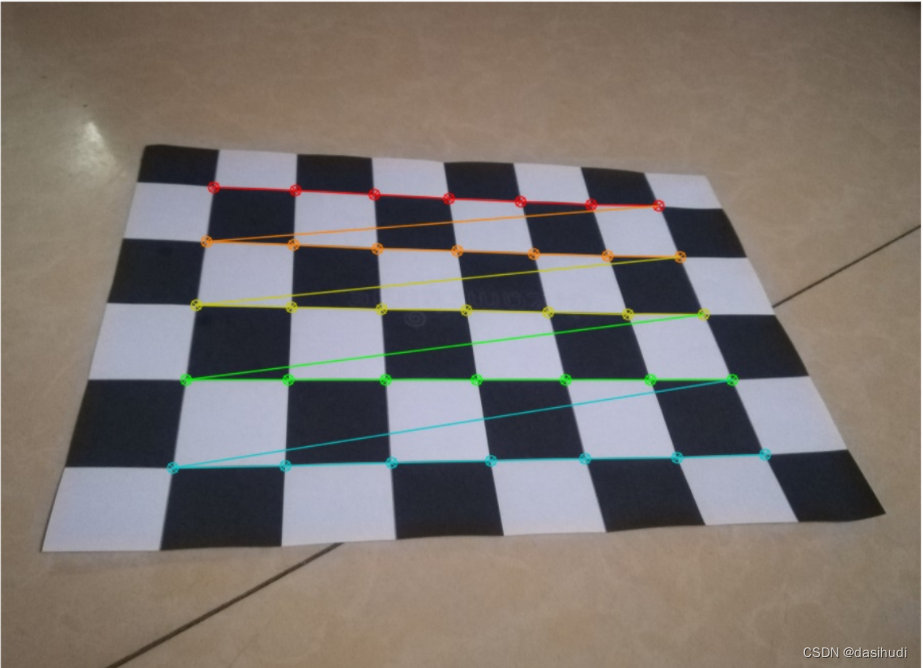
其中5.jpg没有被检测出来,原图如下:

可以明显看到这张图片里棋盘格的四个角都翘起来了,边缘不平整,不平整的图片,检测效果差,精度不高。
内部参数计算结果

从内部参数结果可知道我手机的相机参数: 归一化焦距fx=937.31370089;fy=926.55684557 ; 像主点的坐标:Cx=461.1835826,Cy=207.82166762。
外部参数计算结果(控制台输出)
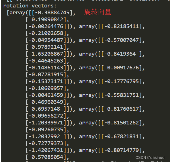

平均重投影误差

平均重投影误差可以用于评估标定效果的好坏,一般来说结果小于0.5可认为标定效果较好,但我这组数据的实验结果超过0.5,即标定效果不够理想,我想原因与我的棋盘格制作有关,我没有找到合适的硬纸板将打印好的棋盘格平整的填在上面,所以A4纸的周边不够平整,有些弯曲;我的棋盘格是网上下载的图片,打印到A4纸上,边缘的黑白格与中间的黑白格大小有一点差异。
五、实验总结
代码中的行列数据是自己自作的棋盘格的行列各-1
注意尺寸的单位是m
当图片像素过高时,运行代码会报错:

将所有数据的像素值都降低再运行,就不会报错了(我这里是将3000多的像素改为900)
标定效果不好与棋盘格是否标准和平整有关,表面褶皱,弯曲的棋盘格,实验效果会比标准的差很多
拍照尽量不要有反光的现象,因为反光的地方成像偏白色,影响标定效果
版权归原作者 dasihudi 所有, 如有侵权,请联系我们删除。