
lvs DR****模式+基于五台服务器部署keepalived + lvs DR模式架构(前端带路由)负载均衡的高可用集群
DR****模式一:
客户端:172.20.26.167
LVS服务器:172.20.26.198
后端服务器:172.20.26.218
后端服务器:172.20.26.210
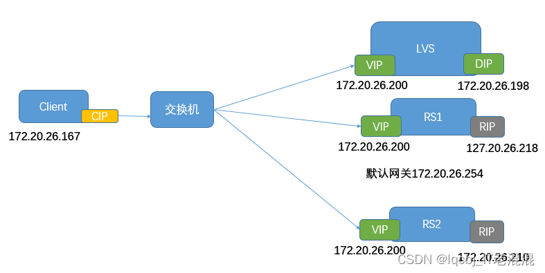
两台后端服务器
yum install nginx tcpdump -y
echo "this is 26.218 page" > /usr/share/nginx/html/index.html
echo "this is 26.210 page" > /usr/share/nginx/html/index.html
启动nginx服务
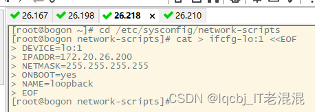
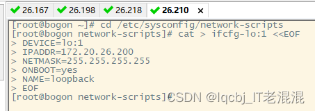
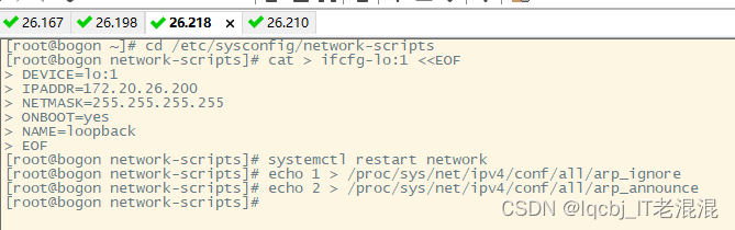
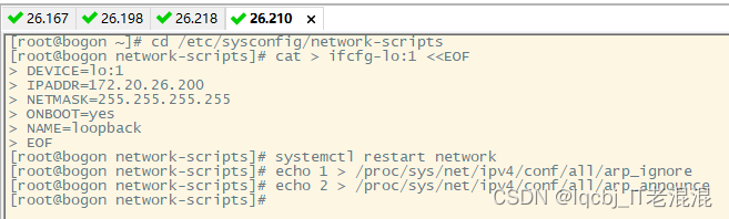
在218、210服务器配置VIP:
cd /etc/sysconfig/network-scripts
cat > ifcfg-lo:1 <<EOF
DEVICE=lo:1
IPADDR=172.20.26.200
NETMASK=255.255.255.255
ONBOOT=yes
NAME=loopback
EOF
重启网络服务
systemctl restart network
配置arp抑制:
echo 1 > /proc/sys/net/ipv4/conf/all/arp_ignore
echo 2 > /proc/sys/net/ipv4/conf/all/arp_announce
在172.20.26.198LVS服务器上配置调度器VIP:
cd /etc/sysconfig/network-scripts
cat > ifcfg-ens34 <<EOF
TYPE=ethernet
BOOTPROTO=none
DEVICE=ens34
ONBOOT=yes
IPADDR=172.20.26.200
PREFIX=24
GATEWAY=172.20.26.254
EOF
重启网络服务
systemctl restart network
在172.20.26.198LVS服务器上安装ipvsadm
yum install ipvsadm -y
配置LVS:
#添加集群服务,调度方式如果不指定,默认是wlc
ipvsadm -A -t 172.20.26.200:80
添加后端真实服务器,工作模式如果不指定,默认是DR模式,-m为NAT模式,如需指定使用-g
ipvsadm -a -t 172.20.26.200:80 -r 172.20.26.218
ipvsadm -a -t 172.20.26.200:80 -r 172.20.26.210
#查看lvs配置
ipvsadm –Ln
访问测试:
[root@node2 ~]# curl 172.20.26.200
this is 26.218 page
[root@node2 ~]# curl 192.168.75.200
this is 26.210 page
DR****模式二

基于六台服务器部署keepalived + lvs DR模式架构(前端带路由)负载均衡的高可用集群;
修改网络模式前将所需软件包安装完成
客户端机器,网卡模式为桥接模式
路由器上开启数据包的转发:
echo 1 > /proc/sys/net/ipv4/ip_forward
两台后端服务器:
yum install nginx -y 安装nginx
yum install tcpdump -y 安装抓包工具
echo "this is RS1.152.129 pages" > /usr/share/nginx/html/index.html
echo "this is RS2.152.128 pages" > /usr/share/nginx/html/index.html
两台LVS服务器A、B:
yum install ipvsadm -y
yum install keepalived -y
echo 1 > /proc/sys/net/ipv4/ip_forward
实验环境各台服务器网络配置:
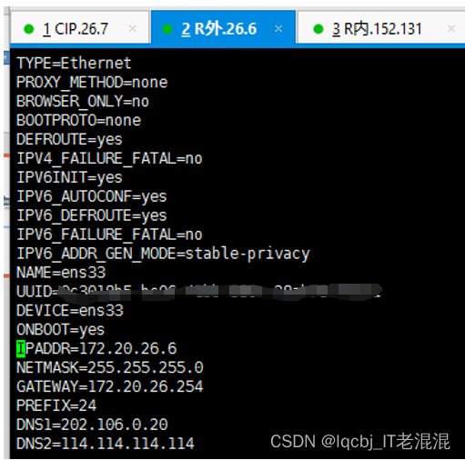
1、CIP服务器的网关设置为R外IP(172.20.26.6)

2、充当路由器的服务器,R外的网关设置为物理机的网关地址172.20.26.254
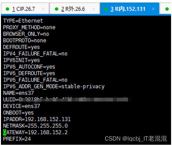
充当路由器的服务器,R内的网关设置为仅主机模式的默认网关地址192.168.152.2
3****、LVS服务器A的VIP网关设置为路由器R内的IP地址
**VIP1:**192.168.152.200
cat > /etc/sysconfig/network-scripts/ifcfg-ens33:1 <<EOF
TYPE="Ethernet"
BOOTPROTO="none"
DEVICE="ens33:1"
ONBOOT="yes"
GATEWAY=192.168.152.131
IPADDR=192.168.152.200
PREFIX=24
EOF

LVS****服务器A的DIP网关设置为路由器R内的IP地址
DIP1****:192.168.152.130
cat > /etc/sysconfig/network-scripts/ifcfg-ens33 <<EOF
TYPE="Ethernet"
BOOTPROTO="none"
DEVICE="ens33"
ONBOOT="yes"
GATEWAY=192.168.152.131
IPADDR=192.168.152.130
PREFIX=24
EOF

4****、LVS服务器B的VIP网关设置为路由器R内的IP地址
**VIP2:**192.168.152.201
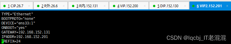
cat > /etc/sysconfig/network-scripts/ifcfg-ens33:1 <<EOF
TYPE="Ethernet"
BOOTPROTO="none"
DEVICE="ens33:1"
ONBOOT="yes"
GATEWAY=192.168.152.131
IPADDR=192.168.152.201
PREFIX=24
EOF
LVS****服务器B的DIP网关设置为路由器R内的IP地址
DIP2****:192.168.152.132
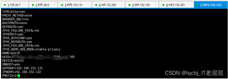
cat > /etc/sysconfig/network-scripts/ifcfg-ens33 <<EOF
TYPE="Ethernet"
BOOTPROTO="none"
DEVICE="ens33"
ONBOOT="yes"
GATEWAY=192.168.152.131
IPADDR=192.168.152.132
PREFIX=24
EOF
5****、两台后端真实服务器的网关设置为路由器R内的IP地址
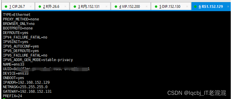
配置后端的VIP:
cat > /etc/sysconfig/network-scripts/ifcfg-lo:1 <<EOF
DEVICE=lo:1
IPADDR=192.168.152.200
NETMASK=255.255.255.255
ONBOOT=yes
NAME=loopback
EOF
抑制arp:
echo 1 > /proc/sys/net/ipv4/conf/all/arp_ignore
echo 2 > /proc/sys/net/ipv4/conf/all/arp_announce

配置后端的VIP:
cat > /etc/sysconfig/network-scripts/ifcfg-lo:1 <<EOF
DEVICE=lo:1
IPADDR=192.168.152.200
NETMASK=255.255.255.255
ONBOOT=yes
NAME=loopback
EOF
抑制arp:
echo 1 > /proc/sys/net/ipv4/conf/all/arp_ignore
echo 2 > /proc/sys/net/ipv4/conf/all/arp_announce
各台服务器均能相互ping通(各台服务器selinux关闭、firewalld关闭,开机启动禁用)。
LVS****服务器A、B上配置ipvsadm
配置LVS:
ipvsadm -A -t 192.168.152.200:80 -s rr
ipvsadm -a -t 192.168.152.200:80 -r 192.168.152.129
ipvsadm -a -t 192.168.152.200:80 -r 192.168.152.128
开启数据包的转发:
echo 1 > /proc/sys/net/ipv4/ip_forward
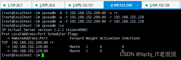
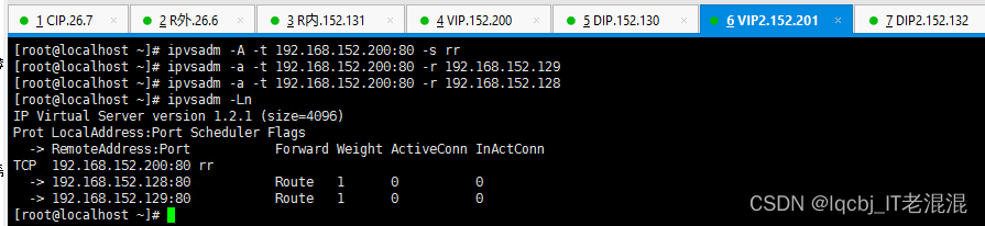
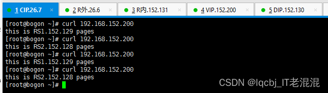
在客户端上访问后端资源
Curl 192.168.152.200 因为设置为rr 轮询方式,各自轮询访问后端服务器
两台LVS服务器上配置keepalived高可用
MASTER:
! Configuration File for keepalived
global_defs {
router_id LVS_MASTER
}
vrrp_instance VI_1 {
state MASTER

interface ens33

virtual_router_id 51

priority 100

advert_int 1

authentication {

    auth_type PASS

    auth_pass 1111

}

virtual_ipaddress {

    192.168.152.200

}
}
virtual_server 192.168.152.200 80 {
delay_loop 6

lb_algo rr

lb_kind DR

persistence_timeout 50

protocol TCP

sorry_server 192.168.152.200 80
real_server 192.168.152.129 80 {
    weight 1

    HTTP_GET {

      url {

        path /

        status_code 200

        }

        connect_timeout 3

        nb_get_retry 3

        delay_before_retry 3

    }

}
real_server 192.168.152.128 80 {
    weight 1

    HTTP_GET {

      url {

        path /

        status_code 200

        }

        connect_timeout 3

        nb_get_retry 3

        delay_before_retry 3

    }

}
}
BACKUP:
! Configuration File for keepalived
global_defs {
router_id LVS_BACKUP
}
vrrp_instance VI_1 {
state BACKUP

interface ens33

virtual_router_id 51

priority 90

advert_int 1

authentication {

    auth_type PASS

    auth_pass 1111

}

virtual_ipaddress {

    192.168.152.200

}
}
virtual_server 192.168.152.200 80 {
delay_loop 6

lb_algo rr

lb_kind DR

persistence_timeout 50

protocol TCP

sorry_server 192.168.152.200 80
real_server 192.168.152.129 80 {
    weight 1

    HTTP_GET {

      url {

        path /

        status_code 200

        }

        connect_timeout 3

        nb_get_retry 3

        delay_before_retry 3

    }

}
real_server 192.168.152.128 80 {
    weight 1

    HTTP_GET {

      url {

        path /

        status_code 200

        }

        connect_timeout 3

        nb_get_retry 3

        delay_before_retry 3

    }

}
}
版权归原作者 lqcbj_IT老混混 所有, 如有侵权,请联系我们删除。