
Packet Tracer - 第 2 层 VLAN 安全
目标
· 在 SW-1 和 SW-2 之间连接新的冗余链路。
· 启用中继,并在 SW-1 和 SW-2 之间的新中继链路上 配置安全。
· 创建新的管理 VLAN (VLAN 20) 并将管理 PC 连接到 该 VLAN。
· 实施 ACL 以阻止外部用户访问 管理 VLAN。
拓扑图

背景/ 场景
目前,公司的网络使用两个 独立的 VLAN 进行设置:VLAN 5 和 VLAN 10。此外,使用本征 VLAN 15 配置 所有中继端口。网络管理员想要在 交换机 SW-1 和 SW-2 之间添加冗余链路。链路必须启用中继,并且所有 安全要求应实施到位。
此外,网络管理员想要将 管理 PC 连接到交换机 SW-A。管理员想要让 管理 PC 连接到所有交换机和路由器,但不想任何 其他设备连接到管理 PC 或交换机。出于管理目的, 管理员想要创建新的 VLAN 20。
所有设备都已采用以下信息进行预配置:
o 启用 加密密码:ciscoenpa55
o 控制台 密码:ciscoconpa55
o SSH 用户名和密码:SSHadmin/ciscosshpa55
第 1 部分:验证 连接。
步骤 1:验证 C2 (VLAN 10) 和 C3 (VLAN 10) 之间的连接。


步骤 2:验证 C2 (VLAN 10) 和 D1 (VLAN 5) 之间的连接。


注意:如果使用简单的 PDU GUI 数据包,请确保执行 ping 操作两次以允许进行 ARP。
第 2 部分:创建 SW-1 和 SW-2 之间的冗余链路
步骤 1:连接 SW-1 和 SW-2。
使用交叉电缆,将 SW-1 上的端口 F0/23 连接到 SW-2 上的端口 F0/23。

步骤 2:启用中继,包括 SW-1 和 SW-2 之间的链路上的所有中继安全 机制。
已在所有现有 中继接口上配置了中继。必须为中继配置新的链路,包括所有 中继安全机制。在 SW-1 和 SW-2 上,将端口设置为 中继,将本征 VLAN 15 分配给中继端口,并禁用自动协商功能。
SW-1(config)#interface f0/23
SW-1(config-if)#switchport mode trunk
SW-1(config-if)#switchport trunk native vlan 15
SW-1(config-if)#switchport nonegotiate
SW-1(config-if)#no shutdown
SW-2(config)#interface f0/23
SW-2(config-if)#switchport mode trunk
SW-2(config-if)#switchport trunk native vlan 15
SW-2(config-if)#switchport nonegotiate
SW-2(config-if)#no shutdown
第 3 部分:启用 VLAN 20 作为管理 VLAN
网络管理员想要使用管理 PC 访问所有交换机和 路由设备。出于安全考虑,管理员 想要确保所有托管设备均位于单独的 VLAN 上。
步骤 1:在 SW-A 上启用管理 VLAN (VLAN 20)。
- 在 SW-A 上启用 VLAN 20。
SW-A(config)#vlan 20
SW-A(config-vlan)#exit
创建接口 VLAN 20 并分配 192.168.20.0/24 网络中的一个 IP 地址。
SW-A(config)#interface vlan 20
SW-A(config-if)#
%LINK-5-CHANGED: Interface Vlan20, changed state to up
%LINEPROTO-5-UPDOWN: Line protocol on Interface Vlan20, changed state to up
SW-A(config-if)#ip address 192.168.20.1 255.255.255.0
步骤 2:在所有其他 交换机上启用同一个管理 VLAN。
在以下所有交换机上创建管理 VLAN:****SW-B****、****SW-1****、****SW-2**** 和 ****Central****。
SW-B(config)#vlan 20
SW-B(config-vlan)#exit
SW-1(config)#vlan 20
SW-1(config-vlan)#exit
SW-2(config)#vlan 20
SW-2(config-vlan)#exit
Central(config)#vlan 20
Central(config-vlan)#exit
- 在所有交换机上创建接口 VLAN 20 并分配 192.168.20.0/24 网络中 的一个 IP 地址。
SW-B(config)#interface vlan 20
SW-B(config-if)#ip address 192.168.20.2 255.255.255.0
SW-1(config)#interface vlan 20
SW-1(config-if)#ip address 192.168.20.3 255.255.255.0
SW-2(config)#interface vlan 20
SW-2(config-if)#ip address 192.168.20.4 255.255.255.0
Central(config)#interface vlan 20
Central(config-if)#ip address 192.168.20.5 255.255.255.0
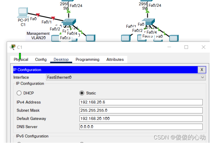
步骤 3:连接并配置管理 PC。
将管理 PC 连接到 SW-A 端口 F0/1 ,并确保向其分配了 192.168.20.0/24 网络中的可用 IP 地址。
步骤 4:在 SW-A 上,确保管理 PC 是 VLAN 20 的组成部分。
接口 F0/1 必须是 VLAN 20 的一部分。
SW-A(config)#interface f0/1
SW-A(config-if)#switchport access vlan 20
SW-A(config-if)#no shutdown
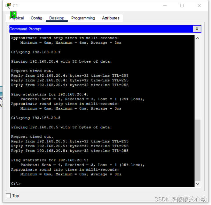
步骤 5:验证管理 PC 与所有 交换机的连接。
管理 PC 应能 ping 通 SW-A、SW-B、 SW-1、SW-2 和 Central。


第 4 部分:启用 管理 PC 以访问路由器 R1
步骤 1:在路由器 R1 上启用新的子接口。
- 创建子接口 g0/0.3 并将封装设置为 dot1q 20 以 用于 VLAN 20。
R1(config)#interface g0/0.3
R1(config-subif)#encapsulation dot1q 20
- 分配 192.168.20.0/24 网络中的一个 IP 地址。
R1(config)#interface g0/0.3
R1(config-subif)#ip address 192.168.20.100 255.255.255.0
步骤 2:验证管理 PC 和 R1 之间的连接。
务必在管理 PC 上配置默认网关以允许连接。
步骤 3:启用安全性。
虽然管理 PC 必须能够访问路由器, 但是其他 PC 不能访问管理 VLAN。
创建一个只允许管理 PC 访问路由器的 ACL。
R1(config)#access-list 101 deny ip any 192.168.20.0 0.0.0.255
R1(config)# access-list 101 permit ip any any
R1(config)#access-list 102 permit ip host 192.168.20.6 any
将该 ACL 应用到正确的接口。
R1(config)#interface g0/0.1
R1(config-subif)#ip access-group 101 in
R1(config-subif)#interface g0/0.2
R1(config-subif)#ip access-group 101 in
R1(config-subif)#line vty 0 4
R1(config-line)#access-class 102 in
注意:可以通过多种方式创建 ACL 以实现必要的安全性。因此,对此练习的 这一部分进行评分时基于正确的连接要求。 管理 PC 必须能够连接到所有交换机和路由器。所有 其他 PC 都不能连接到管理 VLAN 中的任何设备。
步骤 4:验证安全。
a. 验证只有管理 PC 可访问路由器。使用 SSH 访问 R1 ,使用用户名 SSHadmin 和密码 ciscosshpa55。
PC> ssh -l SSHadmin 192.168.20.100

从管理 PC ping 通 ****SW-A****、****SW-B**** 和 ****R1****。 ping 操作是否成功?说明原因。

ping 应该已成功,因为 192.168.20.0 网络中的所有设备都应该能够相互 ping 操作。VLAN20 中的设备不需要通过路由器进行路由。
- 从 D1 ping 通管理 PC。ping 操作是否成功? 说明原因。


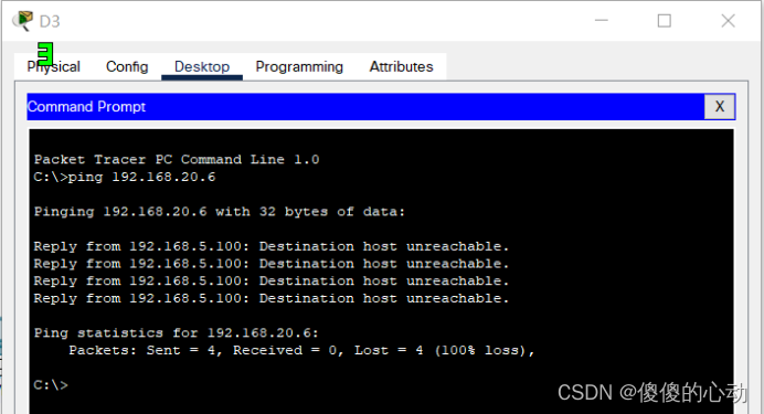
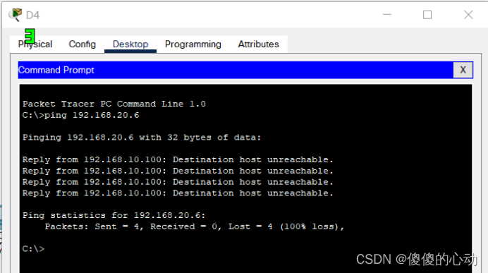
ping 应该失败,因为要使不同 VLAN 中的设备成功 ping VLAN20 中的设备,必须对其进行路由。路由器具有阻止所有数据包访问 192.168.20.0 网络的 ACL****。
步骤 5:检查结果。
完成比例应为 100%。点击 Check Results(检查结果)以查看反馈并验证已完成的所需组件。
如果所有组件似乎都是正确的,但练习 仍显示未完成,则可能是由于验证 ACL 工作原理的连接测试 造成的。
实验具体步骤:
SW-1:
SW-1>en

Password:

SW-1#conf t

Enter configuration commands, one per line. End with CNTL/Z.

SW-1(config)#interface f0/23

SW-1(config-if)#switchport mode trunk

SW-1(config-if)#switchport trunk native vlan 15

SW-1(config-if)#switchport nonegotiate

SW-1(config-if)#no shutdown

%LINK-5-CHANGED: Interface FastEthernet0/23, changed state to down

SW-1(config-if)#exit

SW-1(config)#vlan 20

SW-1(config-vlan)#exit

SW-1(config)#interface vlan 20

SW-1(config-if)#

%LINK-5-CHANGED: Interface Vlan20, changed state to up

%LINEPROTO-5-UPDOWN: Line protocol on Interface Vlan20, changed state to up

SW-1(config-if)#ip address 192.168.20.3 255.255.255.0

SW-1(config-if)#exit

SW-1(config)#end

SW-1#

%SYS-5-CONFIG_I: Configured from console by console

SW-1#wr

Building configuration...

[OK]

SW-1#
SW-2:
SW-2>en

Password:

SW-2#conf t

Enter configuration commands, one per line. End with CNTL/Z.

SW-2(config)#interface f0/23

SW-2(config-if)#switchport mode trunk

SW-2(config-if)#switchport trunk native vlan 15

SW-2(config-if)#switchport nonegotiate

SW-2(config-if)#no shutdown

%LINK-5-CHANGED: Interface FastEthernet0/23, changed state to down

SW-2(config-if)#exit

SW-2(config)#vlan 20

SW-2(config-vlan)#exit

SW-2(config)#interface vlan 20

SW-2(config-if)#

%LINK-5-CHANGED: Interface Vlan20, changed state to up

%LINEPROTO-5-UPDOWN: Line protocol on Interface Vlan20, changed state to up

SW-2(config-if)#ip address 192.168.20.4 255.255.255.0

SW-2(config-if)#exit

SW-2(config)#end

SW-2#

%SYS-5-CONFIG_I: Configured from console by console

SW-2#wr

Building configuration...

[OK]

SW-2#
SW-A:
SW-A>en

Password:

SW-A#conf t

Enter configuration commands, one per line. End with CNTL/Z.

SW-A(config)#interface f0/1

SW-A(config-if)#switchport access vlan 20

SW-A(config-if)#no shutdown

SW-A(config-if)#

%LINK-5-CHANGED: Interface FastEthernet0/1, changed state to up

%LINEPROTO-5-UPDOWN: Line protocol on Interface FastEthernet0/1, changed state to up

SW-A(config-if)#exit

SW-A(config)#end

SW-A#

%SYS-5-CONFIG_I: Configured from console by console

SW-A#wr

Building configuration...

[OK]

SW-A#
SW-B:
SW-B>en

Password:

SW-B#conf t

Enter configuration commands, one per line. End with CNTL/Z.

SW-B(config)#vlan 20

SW-B(config-vlan)#exit

SW-B(config)#interface vlan 20

SW-B(config-if)#

%LINK-5-CHANGED: Interface Vlan20, changed state to up

%LINEPROTO-5-UPDOWN: Line protocol on Interface Vlan20, changed state to up

SW-B(config-if)#ip address 192.168.20.2 255.255.255.0

SW-B(config-if)#exit

SW-B(config)#end

SW-B#

%SYS-5-CONFIG_I: Configured from console by console

SW-B#wr

Building configuration...

[OK]

SW-B#
Central:
Central>en

Password:

Central#conf t

Enter configuration commands, one per line. End with CNTL/Z.

Central(config)#vlan 20

Central(config-vlan)#exit

Central(config)#interface vlan 20

Central(config-if)#

%LINK-5-CHANGED: Interface Vlan20, changed state to up

%LINEPROTO-5-UPDOWN: Line protocol on Interface Vlan20, changed state to up

Central(config-if)#ip address 192.168.20.5 255.255.255.0

Central(config-if)#exit

Central(config)#end

Central#

%SYS-5-CONFIG_I: Configured from console by console

Central#wr

Building configuration...

[OK]

Central#
R1:
R1>en

Password:

R1#conf t

Enter configuration commands, one per line. End with CNTL/Z.

R1(config)#interface g0/0.3

R1(config-subif)#

%LINK-5-CHANGED: Interface GigabitEthernet0/0.3, changed state to up

%LINEPROTO-5-UPDOWN: Line protocol on Interface GigabitEthernet0/0.3, changed state to up

R1(config-subif)#encapsulation dot1q 20

R1(config-subif)#ip address 192.168.20.100 255.255.255.0

R1(config-subif)#exit

R1(config)#access-list 101 deny ip any 192.168.20.0 0.0.0.255

R1(config)# access-list 101 permit ip any any

R1(config)#access-list 102 permit ip host 192.168.20.6 any

R1(config)#interface g0/0.1

R1(config-subif)#ip access-group 101 in

R1(config-subif)#interface g0/0.2

R1(config-subif)#ip access-group 101 in

R1(config-subif)#line vty 0 4

R1(config-line)#access-class 102 in

R1(config-line)#exit

R1(config)#end

R1l#

%SYS-5-CONFIG_I: Configured from console by console

R1#wr

Building configuration...

[OK]

R1#
实验脚本:
SW-1****:
en

ciscoenpa55

conf t

interface f0/23

switchport mode trunk

switchport trunk native vlan 15

switchport nonegotiate

no shutdown

exit

vlan 20

exit

interface vlan 20

ip address 192.168.20.3 255.255.255.0

exit

end

wr
*SW-2:*
en

ciscoenpa55

conf t

interface f0/23

switchport mode trunk

switchport trunk native vlan 15

switchport nonegotiate

no shutdown

exit

vlan 20

exit

interface vlan 20

SW-2(config-if)#

ip address 192.168.20.4 255.255.255.0

exit

end

wr
*SW-A:*
en

ciscoenpa55

conf t

interface f0/1

switchport access vlan 20

no shutdown

exit

end

wr
*SW-B:*
en

ciscoenpa55

conf t

vlan 20

exit

interface vlan 20

ip address 192.168.20.2 255.255.255.0

exit

end

wr
Central****:
en

ciscoenpa55

conf t

vlan 20

exit

interface vlan 20

ip address 192.168.20.5 255.255.255.0

exit

end

wr
R1:
en

ciscoenpa55

conf t

interface g0/0.3

encapsulation dot1q 20

ip address 192.168.20.100 255.255.255.0

exit

access-list 101 deny ip any 192.168.20.0 0.0.0.255

access-list 101 permit ip any any

access-list 102 permit ip host 192.168.20.6 any

interface g0/0.1

ip access-group 101 in

interface g0/0.2

ip access-group 101 in

line vty 0 4

access-class 102 in

exit

end

wr
实验链接:https://pan.baidu.com/s/1FaSOwXenBEfxN3SX-0Rw4w?pwd=6313
提取码:6313
--来自百度网盘超级会员V2的分享
版权归原作者 傻傻的心动 所有, 如有侵权,请联系我们删除。