
程序现象

一、用串口调试助手调试
1.发送指令AT+RST重启模块使应用模式更改生效;
2.发送指令ATE0取消回显
3.使用串口发送指令AT+CWMODE=1设置模块Wi-Fi应用模式为Station模式;
4.发送指令AT+CWJAP ="ssid","pwd"连接AP;
5.发送指令AT+CIPMUX=0设置模块为单路连接模式,模块默认为单路连接模式;
6.发送指令AT+CIPSTART="TCP","api.k780.com",80 与服务器建立TCP连接 ;
7.发送指令AT+CIPMODE=1设置模块传输模式为透传模式;
8.发送指令AT+CIPSEND开启透传模式向服务器发送数据,模块收到此指令后先换行后返回“>”
9.剩下只需要发送 GET http://api.k780.com:88/?app=life.time&appkey=10003&sign=b59bc3ef6191eb9f747dd4e83c99f2a4&format=json&HTTP/1.1\r\n,就能获取到年月时间。 (调用一个网络API接口,这个接口会返回标准网络时间)
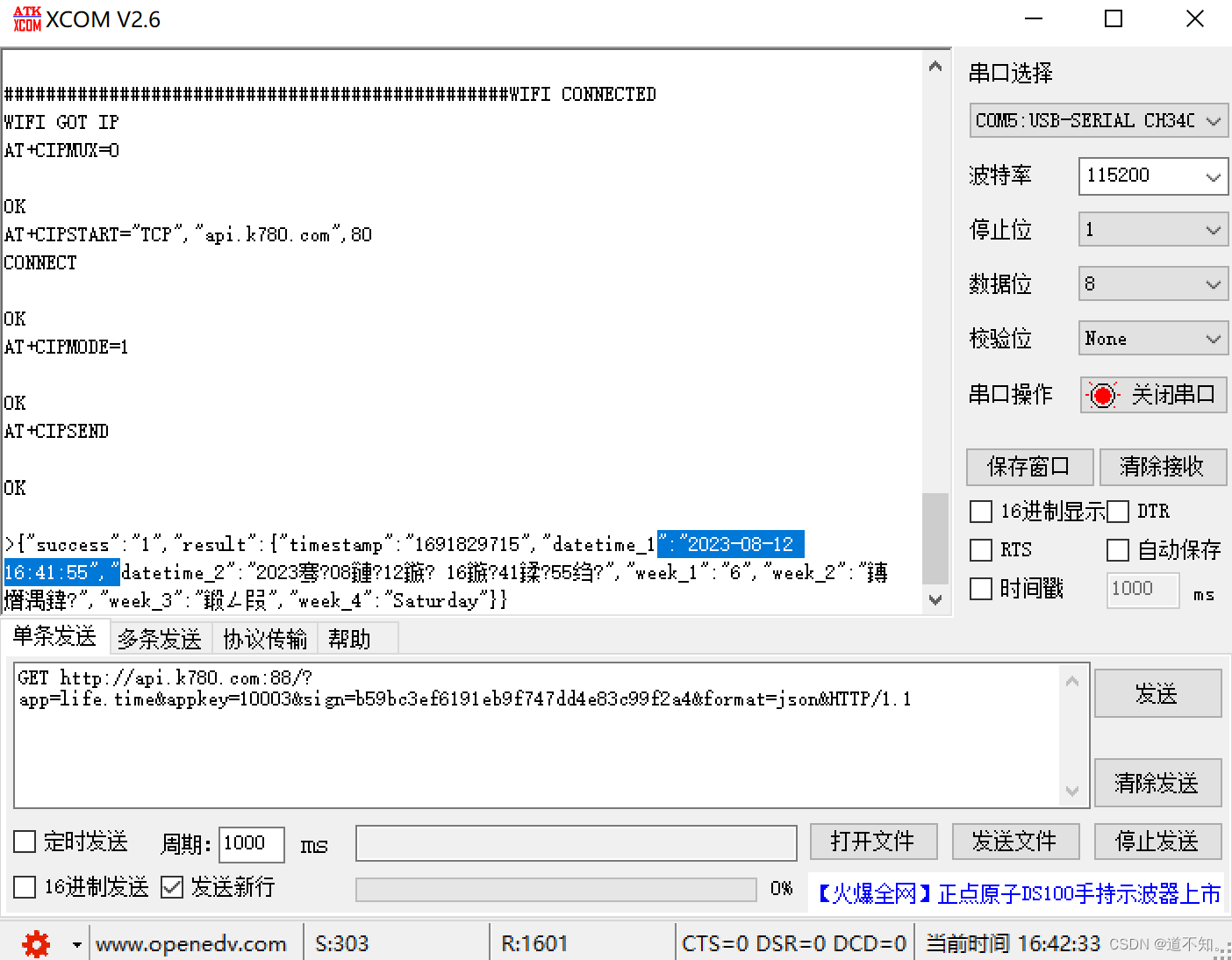
可以看到发送完第九条指令后会收到如上图,所以整体思路:用串口进行通信,发送AT指令,获取到的数据存在Buf中,然后对Buf中的数据解析。获取timestamp后为时间戳,获取datetime_1后为日期时间。
USART串口模块
这一部分的初始化和之前一样,串口接收部分要进行判断如果接收到 '>' ,用Flag标记表示后面调用API后会收到时间戳和时间等数据。
#include "stm32f10x.h"                  // Device header
#include "MyUSART.h"
#include "esp.h"
#include <string.h>

char Buf[512];
unsigned char i;
uint8_t Flag;

void MyUSART_Init(void)
{
    RCC_APB2PeriphClockCmd(RCC_APB2Periph_USART1 ,ENABLE);
    RCC_APB2PeriphClockCmd(RCC_APB2Periph_GPIOA ,ENABLE);

    GPIO_InitTypeDef GPIO_InitStructure;
    GPIO_InitStructure.GPIO_Mode = GPIO_Mode_AF_PP;
    GPIO_InitStructure.GPIO_Pin = GPIO_Pin_9;
    GPIO_InitStructure.GPIO_Speed = GPIO_Speed_50MHz;
    GPIO_Init(GPIOA,&GPIO_InitStructure);
    GPIO_InitStructure.GPIO_Mode = GPIO_Mode_IPU;
    GPIO_InitStructure.GPIO_Pin = GPIO_Pin_10;
    GPIO_InitStructure.GPIO_Speed = GPIO_Speed_50MHz;
    GPIO_Init(GPIOA,&GPIO_InitStructure);

    USART_InitTypeDef USART_InitStructure;
    USART_InitStructure.USART_BaudRate = 115200;
    USART_InitStructure.USART_HardwareFlowControl =USART_HardwareFlowControl_None;
    USART_InitStructure.USART_Mode = USART_Mode_Rx | USART_Mode_Tx;
    USART_InitStructure.USART_Parity =USART_Parity_No ;
    USART_InitStructure.USART_StopBits = USART_StopBits_1;
    USART_InitStructure.USART_WordLength = USART_WordLength_8b;
    USART_Init (USART1,&USART_InitStructure);

    NVIC_PriorityGroupConfig(NVIC_PriorityGroup_2);
    NVIC_InitTypeDef NVIC_InitStructure;
    NVIC_InitStructure.NVIC_IRQChannel =USART1_IRQn;
    NVIC_InitStructure.NVIC_IRQChannelCmd = ENABLE;
    NVIC_InitStructure.NVIC_IRQChannelPreemptionPriority = 1;
    NVIC_InitStructure.NVIC_IRQChannelSubPriority = 0;
    NVIC_Init(&NVIC_InitStructure);

    USART_ITConfig(USART1,USART_IT_RXNE,ENABLE);
    USART_Cmd(USART1,ENABLE);

}
void MyUSART_SendString(char* str)
{
    uint8_t stri=0;
    while(str[stri] != '\0')
        USART_SendData (USART1,str[stri++]);
}
void USART1_IRQHandler()
{
    if(USART_GetITStatus(USART1,USART_IT_RXNE))
    {
        Buf[i++]=USART_ReceiveData(USART1);
        if(Buf[i-1] == '>')
        {
            Flag=1;
        }
        else if((Buf[i-2]=='\r')&&(Buf[i-1]=='\n'))
        {
            Buf[i-2]='\0';
            i = 0;
        }
        USART_ClearITPendingBit(USART1,USART_IT_RXNE);
    }
}
ESP8266WIFI模块
这一部分初始化操作发送AT指令,在主函数中根据返回的数字可以判断哪里有问题
Comman_Rec()这个函数用来处理Buf中接收到的数据。
#include "stm32f10x.h"                  // Device header
#include "MyUSART.h"
#include <stdio.h>
#include <string.h>
#include "Delay.h"
#include "OLED.H"
#include <stdlib.h>

extern char Buf[512];
const char* WIFI ="GT";
const char* PASS="123456789";
extern uint8_t Flag;
uint32_t timestamp_cnt;
char subdatetime_1[11];
char subdatetime_2[8];
uint32_t temp = 2;

int fputc(int ch,FILE *f )   //printf重定向
{
    USART_SendData(USART1,(uint8_t)ch);
    while(USART_GetFlagStatus (USART1,USART_FLAG_TC) == RESET);
    return ch;
}
char esp_Init(void)
{

    memset(Buf,0,sizeof(Buf));
    printf("AT+RST\r\n");
    Delay_ms(2000);

    memset(Buf,0,sizeof(Buf));
    printf("ATE0\r\n");    //关闭回显memset(Buf,0,sizeof(Buf));
    Delay_ms(1000);
    if(strcmp(Buf,"OK")!=0 )
        return 1;

    memset(Buf,0,sizeof(Buf));
    printf("AT+CWMODE=1\r\n");
    Delay_ms(50);
    if(strcmp(Buf,"OK")!=0)
        return 2;


    memset(Buf,0,sizeof(Buf));
    printf("AT+CWJAP=\"%s\",\"%s\"\r\n",WIFI,PASS); //连接热点
    Delay_ms(1000);
    if(strcmp(Buf,"OK")!=0)
        return 3;

    memset(Buf,0,sizeof(Buf));
    printf("AT+CIPMUX=0\r\n");
    Delay_ms(500);
    if(strcmp(Buf,"OK")!=0)
        return 4;

    memset(Buf,0,sizeof(Buf));
    printf("AT+CIPSTART=\"TCP\",\"api.k780.com\",80\r\n");
    Delay_ms(500);
    if(strcmp(Buf,"OK")!=0)
        return 5;

    memset(Buf,0,sizeof(Buf));
    printf("AT+CIPMODE=1\r\n");
    Delay_ms(500);
    if(strcmp(Buf,"OK")!=0)
        return 6;

    memset(Buf,0,sizeof(Buf));
    printf("AT+CIPSEND\r\n");
    Delay_ms(500);
    if(Flag != 1)
        return 7;
    return 0;
}

void ESP_Pub(void)        //当接收到'>'时
{
    if(Flag == 1)
    {
        printf("GET http://api.k780.com:88/?app=life.time&appkey=10003&sign=b59bc3ef6191eb9f747dd4e83c99f2a4&format=json&HTTP/1.1\r\n");
        Delay_ms(2000);
    }
}

void Comman_Rec(void)
{
        char *timestamp_start = strstr(Buf,"timestamp"); // 定位到"timestamp"字段的起始位置
        if (timestamp_start != NULL)
        {
            timestamp_start += (strlen("timestamp")+3); // 跳过"timestamp"
            char timestamp[11];
            strncpy(timestamp, timestamp_start, 10); // 复制10个字符到timestamp数组
            timestamp[10] = '\0';                     // 添加字符串结束符
            timestamp_cnt =atoi(timestamp);        //转换为整数
        }
        char *datetime1_start = strstr(Buf,"datetime_1");
        if (datetime1_start != NULL)
        {
            datetime1_start += (strlen("datetime_1")+3);
            strncpy(subdatetime_1, datetime1_start, 10);
            subdatetime_1[10] = '\0';
            strncpy(subdatetime_2, datetime1_start+11, 7);
            subdatetime_2[7] = '\0';

        }
}
主函数
#include "stm32f10x.h"                  // Device header
#include "OLED.H"
#include <stdio.h>
#include "Delay.h"
#include "MyUSART.H"
#include "esp.h"

extern char Buf[512];
extern uint8_t Flag;
extern uint32_t timestamp_cnt;
extern char subdatetime_1[11];
extern char subdatetime_2[9];

void Init(void)
{
    uint8_t Judge=0;
    OLED_Init();
    OLED_ShowString(1,1,"Linking..");
    Delay_ms(100);
    MyUSART_Init();

    do
    {
        Judge = esp_Init();
        OLED_ShowString(1,1,"code:    ");
        OLED_ShowNum(2,1,Judge,1);
    }while(Judge!=0);

}

int main(void)
{
    Init();
    if(Flag==1)
    {
        OLED_ShowString(1,1,"SUCCESS");
    }
    else
    {
        OLED_ShowString(1,1,"FAIL");
    }
    while(1)
    {
        ESP_Pub();
        Comman_Rec();
        OLED_ShowNum(1,1,timestamp_cnt,10);
        OLED_ShowString(2,1,subdatetime_1);
        OLED_ShowString(3,1,subdatetime_2);

    }

}
注意:这个代码存在的问题是比标准的北京时间慢两秒,因为每次调用网络API接口都会Delay2秒,所以可以只获取时间戳,加上两秒后再根据网上的代码将时间戳转换为具体的时间格式。还可以根据上一节实时时钟的代码实现掉电不丢失的功能。而且有时候显示一会会跳变一下,也有很多问题,我在网上没找到stm32库函数的这个功能实现,还没找到更好的思路。
版权归原作者 道不知。 所有, 如有侵权,请联系我们删除。