
- 网络搭建
根据所给定的拓扑要求,将给定的网络设备互连,搭建物理网络。
2. IP 地址规划
根据要求确定所需子网的数量,每个子网的主机数量,设计适当的编址方案,填写网络地址规划表和设备地址表。
3. 网络设备的安全配置
根据任务书中指出的安全需求,完成数据网络安全配置。
4 数据网络安全测试
安全配置后进行完全效果测试,并分析对应的数据包,理解背后的原理。
一、综合实训内容描述
《网络设备安全配置与管理》综合实训目的在于通过实际案例需求分析完成设备的仿真配置,同时根据需求完成网络安全配置与管理,保证数据网络安全正常运行。从而能在实际工程中理解网络安全通信的含义。
二、实施中需要完成的工作任务
1. 网络搭建
根据所给定的拓扑要求,将给定的网络设备互连,搭建物理网络。
2. IP****地址规划
根据要求确定所需子网的数量,每个子网的主机数量,设计适当的编址方案,填写网络地址规划表和设备地址表。
**3.**网络设备的安全配置
根据任务书中指出的安全需求,完成数据网络安全配置。
4****数据网络安全测试
安全配置后进行完全效果测试,并分析对应的数据包,理解背后的原理。
三、注意事项
项目完成后需要提交相关的WORD规划文件以及相应的配置文档。两份文档存储在文件夹中上交。文件及文件夹命名规则如下:
文档类型格式名称规划表文档WORD综合实训任务书(姓名)配置文档PKT综合实训项目(姓名)
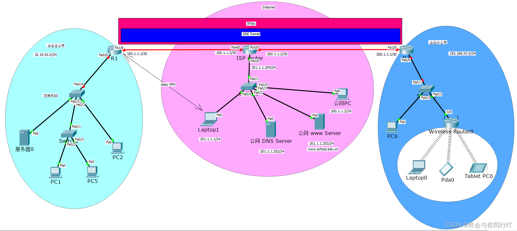
四、网络拓扑图如下
五、根据网络安全需求,进行网络安全配置
(一)基础配置
1、在Packet Tracer中绘制如图所示拓扑图,模拟某公司分隔两地的总公司和分公司之间通过Internet 连接。(注意:XX为学号最后2位)
2、IP地址规划和配置
(1)IP地址规划:
如拓扑图所示,2个分公司内部采用私网地址,Internet采用公网地址,地址表规划如下:
设备名称接口IP地址网关R1Fa0/010.10.11.254/24Fa1/0100.1.1.1/30tunnel1.1.1.1/24R3Fa0/0192.168.11.254/24Fa1/0200.1.1.1/30tunnel1.1.1.2/24ISP routerFa4/0100.1.1.2/30Fa5/0200.1.1.2/30Fa0/0201.1.1.254/24Server 0Fa010.10.11.1/2410.10.11.254/24PC1Fa010.10.11.2/2410.10.11.254/24PC5Fa010.10.11.3/2410.10.11.254/24PC2Fa010.10.11.4/2410.10.11.254/24Laptop0Fa0201.1.1.1/24201.1.1.254/24公网DNSFa0201.1.1.252/24201.1.1.254/24公网wwwFa0201.1.1.253/24201.1.1.254/24公网PCFa0201.1.1.2/24201.1.1.254/24PC6Fa0192.168.11.1/24192.168.11.254/24
(2)IP地址配置:
按拓扑图地址规划要求:
给各路由器配置对应的IP地址、子网掩码;
给各PC机配置对应的IP地址、子网掩码、网关。
配置命令如下:(注意:配置命令要大概说明其含义)
R1 IP****地址配置
R1> enable                                                    #进入特权模式
R1# configure terminal                                        #进入全局模式
R1(config)# interface fastEthernet 0/0                        #进入fa0/0端口
R1(config-if)# ip address 10.10.11.254 255.255.255.0        #配置IP和子网掩码
R1(config-if)# no shutdown                                     #启用端口
R1(config-if)# exit                                            #退出fa0/0端口
R1(config)# interface fastEthernet 1/0                        #进入fa1/0端口
R1(config-if)# ip address 100.1.1.1 255.255.255.252         #配置IP和子网掩码
R1(config-if)# no shutdown                                     #启用端口
R1(config-if)# exit                                            #退出fa1/0端口
R3 IP****地址配置
R3> enable                                                    #进入特权模式
R3# configure terminal                                        #进入全局模式
R3(config)# interface fastEthernet 0/0                        #进入fa0/0端口
R3(config-if)# ip address 192.168.11.254 255.255.255.0        #配置IP和子网掩码
R3(config-if)# no shutdown                                     #启用端口
R3(config-if)# exit                                            #退出fa0/0端口
R3(config)# interface fastEthernet 1/0                        #进入fa1/0端口
R3(config-if)# ip address 200.1.1.1 255.255.255.252         #配置IP和子网掩码
R3(config-if)# no shutdown                                     #启用端口
R3(config-if)# exit                                            #退出fa1/0端口
ISP****配置
ISP> enable                                                    #进入特权模式
ISP# configure terminal                                     #进入全局模式
ISP(config)# interface fastEthernet 4/0                        #进入fa4/0端口
ISP(config-if)# ip address 100.1.1.2 255.255.255.252        #配置IP和子网掩码
ISP (config-if)# no shutdown                                 #启用端口
ISP(config-if)# exit                                        #退出fa4/0端口
ISP(config)# interface fastEthernet 5/0                        #进入fa5/0端口
ISP(config-if)# ip address 200.1.1.2 255.255.255.252        #配置IP和子网掩码
ISP(config-if)# no shutdown                                 #启用端口
ISP(config-if)# exit                                        #退出fa5/0端口
ISP(config)# interface fastEthernet 0/0                        #进入fa0/0端口
ISP(config-if)# ip address 201.1.1.254 255.255.255.0        #配置IP和子网掩码
ISP(config-if)# no shutdown                                 #启用端口
ISP(config-if)# exit                                        #退出fa0/0端口
3、在总公司和分公司边界路由器上配置默认路由,达到总公司和分公司公网地址互通,配置命令如下:(注意:配置命令要大概说明其含义)
R1****配置默认路由
R1(config)#ip route 0.0.0.0 0.0.0.0 100.1.1.2 #配置默认路由
R3****配置默认路由
R3(config)#ip route 0.0.0.0 0.0.0.0 100.1.1.2 #配置默认路由
4、测试R1和R3的公网地址间的互通性(验证Internet互通),截图如下:(注意:说明为什么)
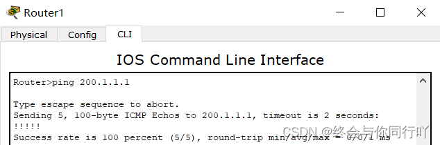
答:可以互通,因为R1配置了默认路由,全部数据包转发给了ISP的Fa4/0端口,而R3配置了默认路由,全部数据包转发给了ISP的Fa5/0端口,最终数据包在同一个路由器的两个端口上,所以可以直接通信。
(二)路由器R1的SSH登录服务配置:
1、SSH登录要求:
在路由器R1上配置SSH登录服务,其中所有的域名、用户名、密码等皆为wtctx-YYY(YYY为姓名缩写)
2、配置命令如下:(注意:配置命令要大概说明其含义)
R1(config)# hostname R1                        #配置ssh前必须修改主机名
R1(config)# ip domain-name wtctx-qh            #给路由器设置域名
R1(config)# crypto key generate rsa            #生成rsa秘钥
R1(config)# line vty 0 15                    #进入vty端口,最多15人同时在线
R1(config-line)# transport input ssh        #启用SSH登录
R1(config-line)# privilege level 15            #设置用户操作等级为最高级
R1(config-line)# login local                #使用本地验证
R1(config-line)# exit                        #退出到全局模式
R1(config)# username wtctx-qh password wtctx-qh    #创建用户名和密码
R1(config)# enable secret wtctx-qh            #设置密文密码
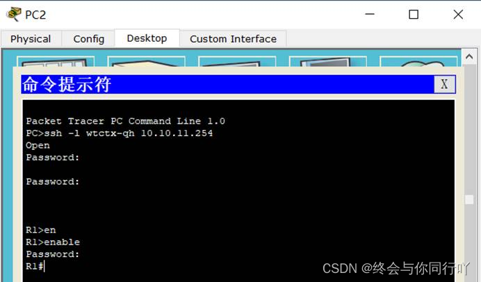
3、测试PC2 SSH登录R1,截图如下:
(三)交换机端口安全配置:
1、在总公司交换机上端口安全要求:
(1)f0/1端口采用静态MAC地址学习方式,指定服务器0的MAC地址,端口最大MAC地址数为?违规处理方式shutdown
(2)f0/2端口采用sticky MAC地址学习方式,端口最大MAC地址数为?违规处理方式restrict
2、相关配置命令如下:(注意:配置命令要大概说明其含义)
Fa0/1****端口配置
Switch> en                                                    #进入特权模式
Switch# configure terminal                                    #进入全局模式
Switch(config)# interface fastEthernet 0/1                    #进入Fa0/1端口
Switch(config-if)# shutdown                                    #关闭端口,清空mac地址表
Switch(config-if)# switchport mode access                    #端口定义为access口
Switch(config-if)# switchport port-security                    #开启端口安全功能
Switch(config-if)# switchport nonegotiate                    #禁用DTP
Switch(config-if)# switchport port-security maximum 1        #设置允许最大地址数为1
Switch(config-if)# switchport port-security mac-address 0090.0C62.168A   #绑定允许接入的地址
Switch(config-if)# switchport port-security violation shutdown           #指定违规处理行为
Switch(config-if)# no shutdown                                       #启用端口
解析:端口最大mac地址数为1即可,由于Fa0/1与服务器0是直连的,绑定服务器0的mac地址即可限制其它设备接入。
Fa0/2****端口配置
Switch> en                                                #进入特权模式
Switch# configure terminal                                    #进入全局模式
Switch(config)# interface fastEthernet 0/2                    #进入Fa0/1端口
Switch(config-if)# shutdown                                    #关闭端口,清空mac地址表
Switch(config-if)# switchport mode access                        #端口定义为access口
Switch(config-if)# switchport port-security                    #开启端口安全功能
Switch(config-if)# switchport nonegotiate                        #禁用DTP
Switch(config-if)# switchport port-security maximum 3            #设置允许最大地址数为3
Switch(config-if)# switchport port-security mac-address sticky    #绑定允许接入的地址
Switch(config-if)# switchport port-security violation restrict    #指定违规处理行为
Switch(config-if)# no shutdown                                #启用端口
解析:端口最大mac地址数为3,通过观察交换机的mac地址表可以看出,交换机一共粘贴到了三个地址,Fa0/2端口下另外一个交换机的Fa0/1号端口的mac地址,和PC1与PC5的mac地址。添加其他设备发现无法通信,表明最大数为3是正确的。
(四)无线局域网安全配置:
在分公司无线路由器上做安全配置:
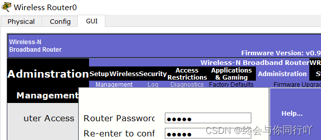
1、基础安全设置:(XX为学号最后2位)
1)修改无线路由器默认的管理密码为:wtctx
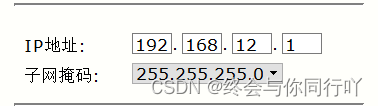
2)修改LAN口地址:192.168.XX+1.1/24
3)修改SSID:wtctx18
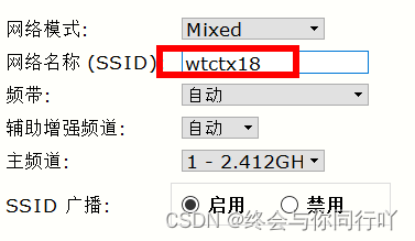
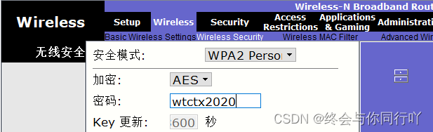
4)无线安全配置:
认证:WPA2-PSK
加密:AES
预共享密钥:wtctx2020
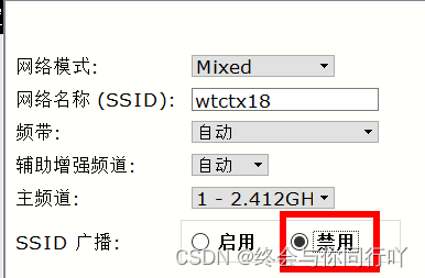
2、进一步安全配置:
1)隐藏SSID
2)无线mac地址过滤
只允许图中3台无线设备laptop0、Smartphone0、Table PC0的mac地址接入,其他不允许
设备mac地址Laptop00001.642A.4045Smartphone00001.4205.D0ACTablet PC00001.C7B0.ED9E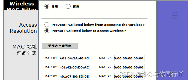
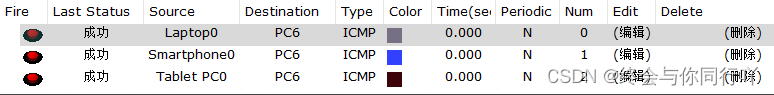
3、测试各无线终端与PC6的连通性,截图显示如下:
(五)GRE over IPSec VPN配置:
1、在企业总公司和分公司间配置GRE over IPSec VPN (企业总公司和分公司间参数一致),要求:
(1)GRE tunnel两端地址分别为:1.1.1.1/24和1.1.1.2/24 ,tunnel编号为120
(2)企业总公司和分公司间运行rip协议或OSPF实现互通
(3)IPSec配置:设置IKE参数,策略优先级为1(预共享验证、DES加密、MD5验证,DH组2,预共享验证密钥为wtctx)
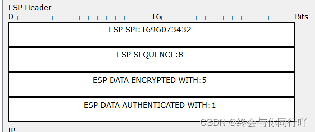
(4)Ipsec SA 参数设置:ESP-DES加密、ESP-MD5-HMAC验证
(5)VPN数据流acl编号为110
(6)transform-set 命名为wtctxset1,crypto map命名为wtctxmap
2、配置如下:(注意:配置命令要大概说明其含义)
R1(config)#interface tunnel 120                    #创建虚拟tunnel端口
R1(config-if)#ip address 1.1.1.1 255.255.255.0        #定义tunnel接口的IP地址
R1(config-if)#tunnel source fastEthernet 1/0        #定义tunnel通道的源地址
R1(config-if)#tunnel destination 200.1.1.1        #定义tunnel通道的目的地址
R1(config)#router rip                            #启用rip路由协议
R1(config-router)#version 2                        #定义rip v2版本
R1(config-router)#no auto-summary                    #关闭自动汇总
R1(config-router)#network 10.10.11.0                #宣告自己的网段
R1(config-router)#network 1.1.1.1                    #宣告自己的网段
R1(config-router)# exit                            #回到全局模式
R1(config)# crypto isakmp enable                        #启用IKE
R1(config)# crypto isakmp policy 1                        #建立IKE策略,优先级为1
R1(config-isakmp)# authentication pre-share                #使用预共享的密码进行身份验证
R1(config-isakmp)# encryption des                        #使用DES加密方式
R1(config-isakmp)# hash md5                            #指定Hash算法为MD5
R1(config-isakmp)# group 2                                #指定秘钥位数,group2安全性更高
R1(config-isakmp)# exit                                #回到全局模式
R1(config)#access-list 110 permit gre host 100.1.1.1 host 200.1.1.1     #定义感兴趣流量
R1(config)# crypto isakmp key wtctx address 200.1.1.1    #设置预共享秘钥和对端IP
R1(config)#crypto ipsec transform-set wtctxset1 esp-des esp-md5-hmac #配置IPSec交换集
R1(config)#crypto map wtctxmap 1 ipsec-isakmp            #创建加密图
R1(config-crypto-map)#set peer 200.1.1.1                #标识对方路由器IP地址
R1(config-crypto-map)#set transform-set wtctxset1        #指定加密图使用的IPSec交换集
R1(config-crypto-map)#match address 110                #用ACL来定义加密的通信
R1(config-crypto-map)#exit                            #回到全局模式
R1(config)#interface fastEthernet 1/0                    #进入Fa1/0端口
R1(config-if)#crypto map wtctxmap                        #应用加密图到接口
R3(config)#interface tunnel 120                    #创建虚拟tunnel端口
R3(config-if)#ip address 1.1.1.2 255.255.255.0        #定义tunnel接口的IP地址
R3(config-if)#tunnel source fastEthernet 1/0        #定义tunnel通道的源地址
R3(config-if)#tunnel destination 100.1.1.1        #定义tunnel通道的目的地址
R3(config)#router rip                            #启用rip路由协议
R3(config-router)#version 2                        #定义rip v2版本
R3(config-router)#no auto-summary                    #关闭自动汇总
R3(config-router)#network 192.168.11.0            #宣告自己的网段
R3(config-router)#network 1.1.1.2                    #宣告自己的网段
R3(config)# crypto isakmp enable                    #启用IKE
R3(config)# crypto isakmp policy 1                #建立IKE策略,优先级为1
R3(config-isakmp)# authentication pre-share        #使用预共享的密码进行身份验证
R3(config-isakmp)# encryption des                    #使用DES加密方式
R3(config-isakmp)# hash md5                        #指定Hash算法为MD5
R3(config-isakmp)# group 2                        #指定秘钥位数,group2安全性更高
R3(config-isakmp)# exit                            #回到全局模式
R3(config)#access-list 110 permit gre host 200.1.1.1 host 100.1.1.1     #定义感兴趣流量
R3(config)# crypto isakmp key wtctx address 100.1.1.1        #设置预共享秘钥和对端IP
R3(config)#crypto ipsec transform-set wtctxset1 esp-des esp-md5-hmac #配置IPSec交换集
R3(config)#crypto map wtctxmap 1 ipsec-isakmp            #创建加密图
R3(config-crypto-map)#set peer 100.1.1.1                #标识对方路由器IP地址
R3(config-crypto-map)#set transform-set wtctxset1        #指定加密图使用的IPSec交换集
R3(config-crypto-map)#match address 110                #用ACL来定义加密的通信
R3(config-crypto-map)#exit                            #回到全局模式
R3(config)#interface fastEthernet 1/0                    #进入Fa1/0端口
R3(config-if)#crypto map wtctxmap                        #应用加密图到接口
3、测试:
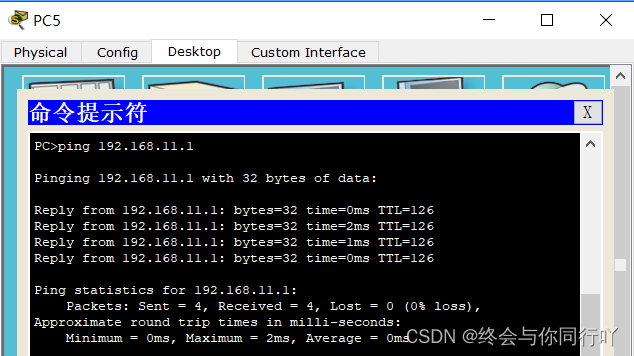
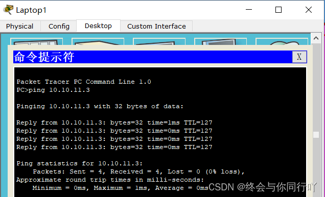
总公司PC5和分公司PC6间以私有地址互访,截图如下:
4、分析GRE over Ipsec VPN的数据包
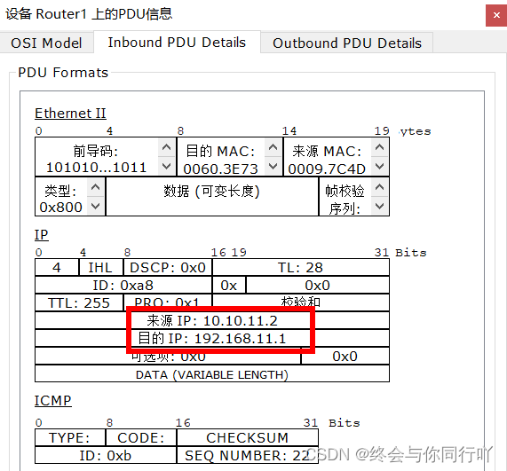
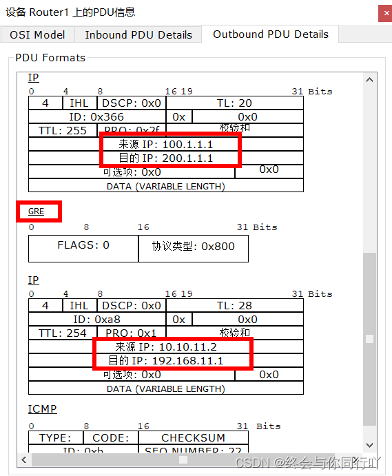
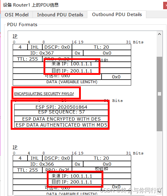
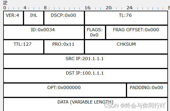
答:可以看到入站前源地址和目的地址都是私网地址,经过路由器,从出站方向可以看到添加了GRE头部,然后添加了公网地址的头部,源地址和目的地址都为公网地址,然后经过IPsec加密,最后添加了公网地址的头部进行传送。
(六)Easy VPN配置:
1、在R1上配置Easy VPN,配置策略要求如下:
(1)设置IKE参数,策略优先级为2(预共享验证、DES加密、MD5验证、DH组2)
(2)启动aaa,设置认证组名为wtc-a,授权组名为wtc-o,用户名和密码为wtc
(3)设置策略组名为wtcgroup、密码为wtckey,地址池为wtcpool,地址范围172.16.1.1—172.16.1.254
(4)设置 transform-set 命名为wtctxset2(ESP-DES加密、ESP-MD5-HMAC验证),动态crypto map命名为wtcdmap,静态crypto map命名为wtctxmap
2、配置命令如下:(注意:配置命令要大概说明其含义)
R1(config)# crypto isakmp policy 2                    ##建立IKE策略,优先级为2
R1(config-isakmp)# authentication pre-share            #使用预共享的密码进行身份验证
R1(config-isakmp)# encryption des                    #使用DES加密方式
R1(config-isakmp)# hash md5                        #指定Hash算法为MD5
R1(config-isakmp)# group 2                            #指定秘钥位数,group2安全性更高
R1(config)# aaa new-model                            #启用aaa
R1(config)# aaa authentication login wtc-a local            #认证
R1(config)# aaa authorization network wtc-o local        #授权
R1(config)# username wtc password wtc                #在交换机本地设置一个用户
R1(config)# ip local pool wtcpool 172.16.1.1 172.16.1.254    #定义地址池
R1(config)# crypto isakmp client configuration group wtcgroup        #配置用户组策略
R1(config-isakmp-group)# key wtckey                            #定义密码
R1(config-isakmp-group)# pool wtcpool                        #定义使用的地址池
R1(config-isakmp-group)# exit                                #回到全局模式
R1(config)# crypto ipsec transform-set wtctxset2 esp-des esp-md5-hmac      #配置IPSec交换集R1(config)# crypto dynamic-map wtcdmap 2                    #定义动态保密图
R1(config-crypto-map)# set transform-set wtctxset2                #设置调用的IPsec交换集
R1(config-crypto-map)# reverse-route                            #路由器必须配置此功能
R1(config-crypto-map)# exit                                    #回到全局模式
R1(config)# crypto map wtctxmap client authentication list wtc-a    #设置认证用户列表
R1(config)# crypto map wtctxmap isakmp authorization list wtc-o    #设置授权用户列表
R1(config)# crypto map wtctxmap client configuration address respond    # VPN地址推送方式
R1(config)# crypto map wtctxmap 2 ipsec-isakmp dynamic wtcdmap    #将动态保密图映射到静态保密图
R1(config-crypto-map)# exit                                    #回到全局模式
R1(config)# interface fastEthernet 1/0                            #进入Fa1/0端口
R1(config-if)# crypto map wtctxmap                            #关联到Fa1/0端口
3、测试:
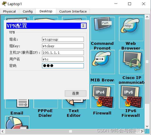
出差员工PC以VPN登录,能访问公总司PC,截图显示
4、分析easy VPN的数据包
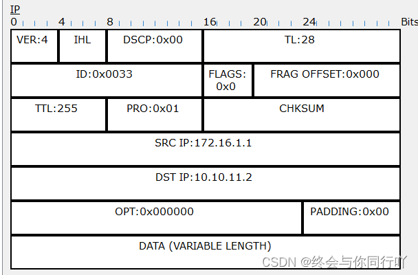
答:位于公网的电脑,登录easy VPN之后会自动获取到一个我们设置的地址池地址,和位于公司总部的电脑进行通信时,首先在公网这边的路由器ISP进站源地址是分配的地址池IP,目的地址为分公司私网地址,出站后添加了ESP头部,然后添加了公网地址头。在总公司路由器进站则是将添加了私网地址头,源地址为公网电脑登录VPN分配的地址池IP,目的地址为总公司内部的私网地址。
(七)NAT配置:
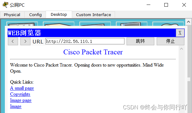
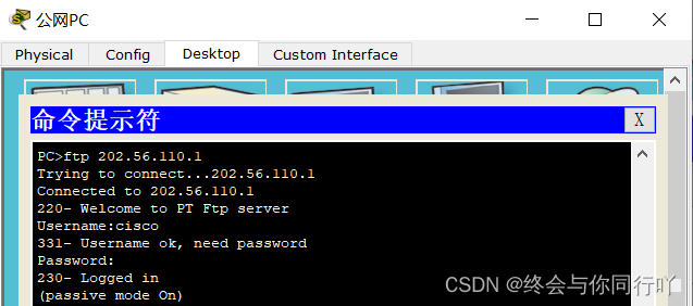
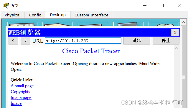
1、在企业总公司边界路由器R1上配置静态一对多nat,实现公网PC能访问内网服务器0的web服务和ftp服务,要求:
内网服务器对应的公网地址为:202.56.110.1
2、在企业总公司边界路由器R1上配置PAT,实现内网用户访问公网WWW服务器和公网PC,要求:
(1)公网IP地址直接为私网接口地址;
(2)私网地址acl编号为1
3、配置命令如下:(注意:配置命令要大概说明其含义)
R1(config)#interface fastEthernet 0/0            #进入Fa0/0端口
R1(config-if)#ip nat inside                    #定义对于NAT来说内部接口
R1(config)#interface fastEthernet 1/0            #进入Fa1/0端口
R1(config-if)#ip nat outside                    #定义对于NAT来说外部接口
R1(config)#ip nat inside source static tcp 10.10.11.1 80 202.56.110.1 80
R1(config)#ip nat inside source static tcp 10.10.11.1 20 202.56.110.1 20
R1(config)#ip nat inside source static tcp 10.10.11.1 21 202.56.110.1 21
ISP(config)#ip route 202.56.110.1 255.255.255.255 100.1.1.1 #配置静态路由
R1(config)#access-list 1 permit 10.10.11.0 0.0.0.255   #acl列表
R1(config)#ip nat inside source list 1 interface fastEthernet 1/0 overload #定义转换源
4、测试:
(1)公网PC能访问总公司内网服务器0的www服务,截图如下:
(2)公网PC能访问总公司内网服务器0的ftp服务,截图如下:
(3)总公司PC能访问公网服务器,截图如下:
版权归原作者 终会与你同行吖 所有, 如有侵权,请联系我们删除。