
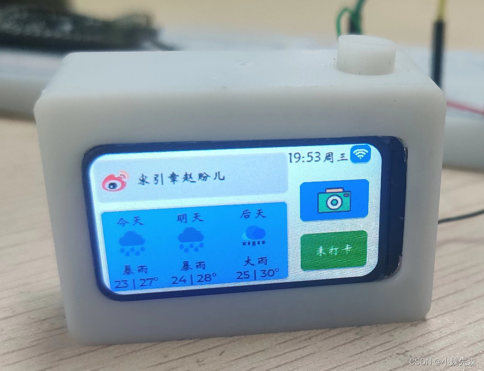
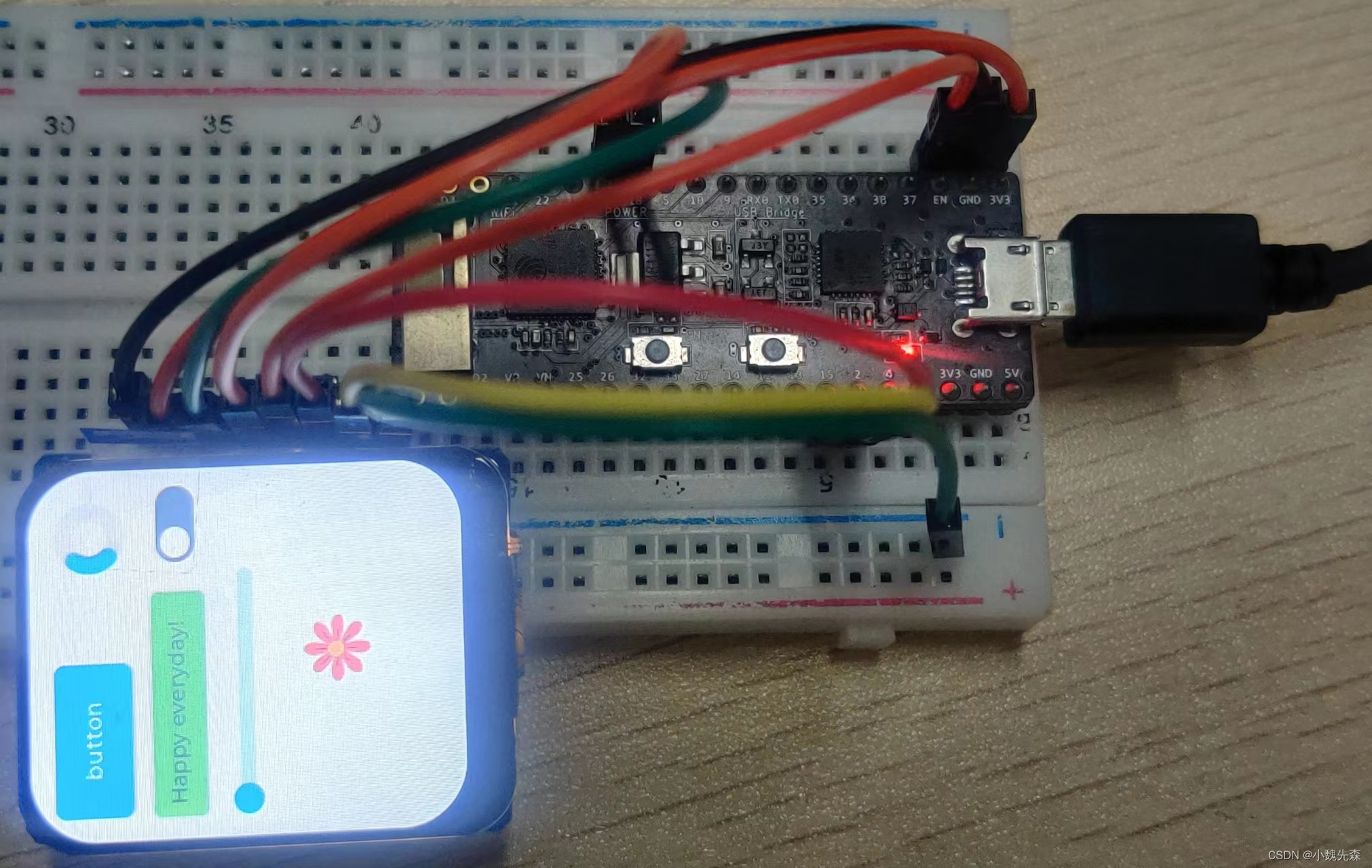
效果展示
小相机,按一下能拍照,并将照片保存在sd卡中。
开发环境
使用的时VSCode+PlatformIO进行开发(强力推荐,用了就回不去了),当然也可以使用ArduinoIDE进行开发。
具体怎么使用上述软件,网上有很多答案,可以自行查找。
使用到的库:TFT_eSPI和
lvgl
一、TFT_eSPI配置
添加该库到项目之后,首先进行编译,可能会出现找不到
SPI.h文件的情况,但是该文件明明存在。
解决办法:在配置文件platformio.ini文件中加入
lib_ldf_mode = deep+,问题得到解决。
配置文件内容如下所示
[env:pico32]
platform = espressif32
board = pico32
framework = arduino
lib_ldf_mode = deep+
lib_deps =
    bodmer/TFT_eSPI@^2.4.75
    lvgl/lvgl@^8.3.1
然后在文件
User_Setup.h中进行如下更改。
1、设置屏幕驱动

使用的屏幕如上图所示,需要将上述文件的第45行进行注释,打开第55行注释,如下图所示,注意上面有说明只能同时定义一个驱动。
// Only define one driver, the other ones must be commented out//#define ILI9341_DRIVER // Generic driver for common displays//#define ILI9341_2_DRIVER // Alternative ILI9341 driver, see https://github.com/Bodmer/TFT_eSPI/issues/1172//#define ST7735_DRIVER // Define additional parameters below for this display//#define ILI9163_DRIVER // Define additional parameters below for this display//#define S6D02A1_DRIVER//#define RPI_ILI9486_DRIVER // 20MHz maximum SPI//#define HX8357D_DRIVER//#define ILI9481_DRIVER//#define ILI9486_DRIVER//#define ILI9488_DRIVER // WARNING: Do not connect ILI9488 display SDO to MISO if other devices share the SPI bus (TFT SDO does NOT tristate when CS is high)#defineST7789_DRIVER// Full configuration option, define additional parameters below for this display
2、设置屏幕尺寸
在程序的第83行下面更改屏幕尺寸,如下图所示。
// For ST7789, ST7735, ILI9163 and GC9A01 ONLY, define the pixel width and height in portrait orientation// #define TFT_WIDTH 80// #define TFT_WIDTH 128// #define TFT_WIDTH 172 // ST7789 172 x 320#defineTFT_WIDTH240// ST7789 240 x 240 and 240 x 320#defineTFT_HEIGHT280
3、定义ESP32引脚
可以使用硬件SPI也可以使用软件模拟SPI,只需要更改相应的引脚号即可
在文件的第203行下面定义ESP32引脚。
ESP32与屏幕链接引脚:
ESP32屏幕23SDA18SCL15CS2DCENRST自定义BL
// For ESP32 Dev board (only tested with ILI9341 display)// The hardware SPI can be mapped to any pins//#define TFT_MISO 19#defineTFT_MOSI23#defineTFT_SCLK18#defineTFT_CS15// Chip select control pin#defineTFT_DC2// Data Command control pin// #define TFT_RST 4 // Reset pin (could connect to RST pin)#defineTFT_RST-1// Set TFT_RST to -1 if display RESET is connected to ESP32 board RST
二、LVGL配置
LVGL官方链接:点击这里
操作步骤:
1、将lvgl库文件夹中的lv_conf_template.h复制粘贴到lvgl文件夹之外,并重命名为
lv_conf.h2、将第15行,
#if 0 改为 #if 1使能代码
3、更改该文件中的第27行,将LV_COLOR_DEPTH改为屏幕的色深值,本屏幕为
16不做更改
4、将第88行#define LV_TICK_CUSTOM定义为
1
三、Example测试
1、测试一
lvgl库中又demos和examples两个文件夹,这两个文件夹中的示例可以用来测试框架是否配置完毕。
操作步骤:
1、将examples文件夹复制到
lvgl/src文件夹中(本测试并未使用example中的例子,小伙伴们可以自行测试),让该部分能够得到编译。
2、将examples/arduino文件夹中的示例
LVGL_Arduino.ino中的
内容,复制到
main.cpp中,将main.cpp中原有内容全部覆盖,但要保留
#include<Arduino.h>3、此时文件会报错,将第10行
#include <lv_demo.h>删除;第
13、14行改为自己的屏幕尺寸(注意要和TFT_eSPi中设置的宽高保持一致)
4、此时依然报错,注释掉my_touchpad_read()函数,此外注释掉第93、94行代码
uint16_t calData[5] = { 275, 3620, 264, 3532, 1 }; tft.setTouch( calData );5、将文件中第
115行
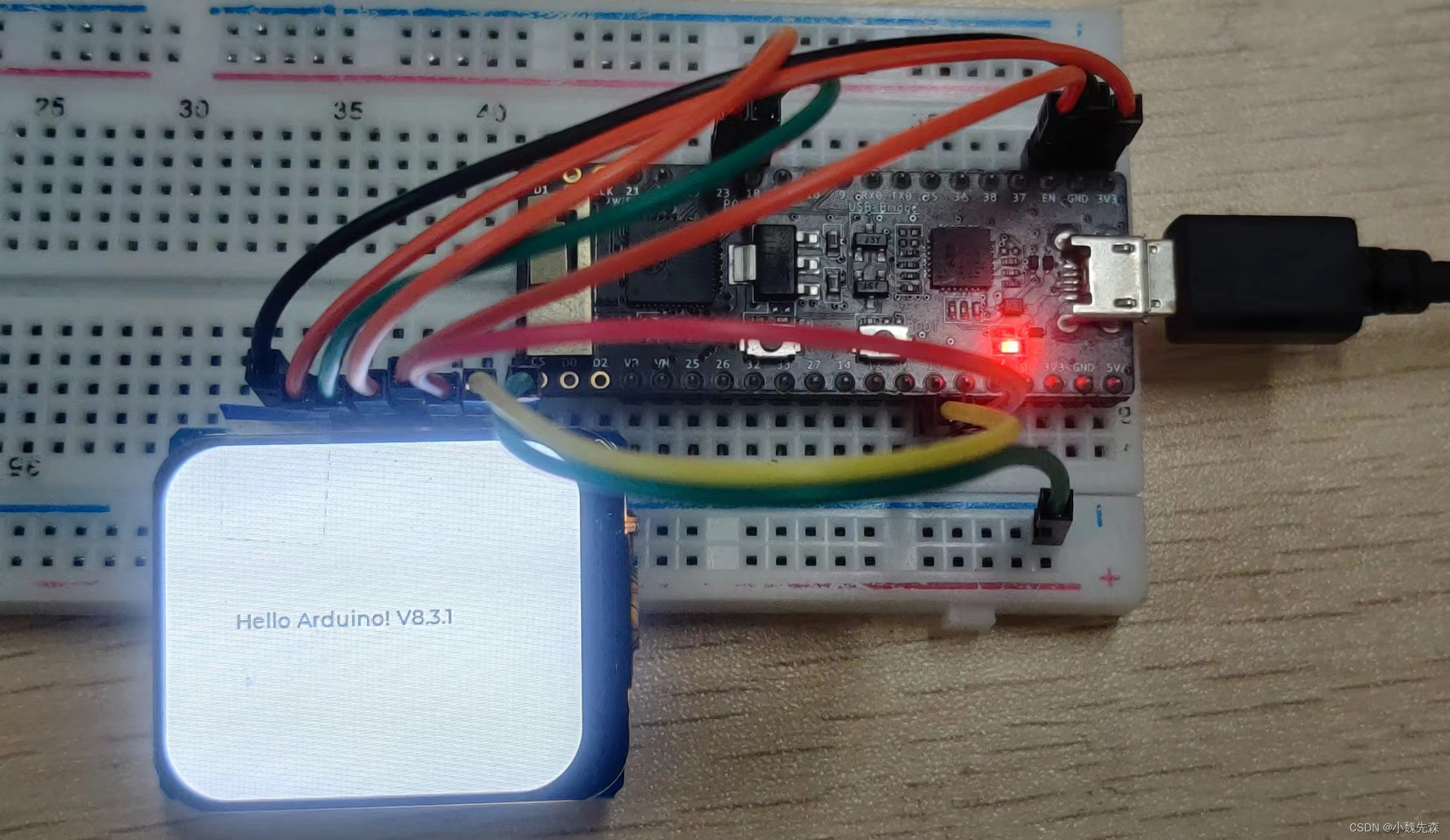
#if 0 改为#if 1,使能label代码,此时运行程序,得到如下结果。如果发现屏幕显示的方向不正确,可以调整第88行的
tft.setRotation( 1 );数值
0、1、2、3分别向不同的方向旋转。
修改后的完整示例代码如下:
#include<Arduino.h>#include<lvgl.h>#include<TFT_eSPI.h>/*If you want to use the LVGL examples,
  make sure to install the lv_examples Arduino library
  and uncomment the following line.
#include <lv_examples.h>
*//*Change to your screen resolution*/staticconstuint16_t screenWidth  =280;staticconstuint16_t screenHeight =240;static lv_disp_draw_buf_t draw_buf;static lv_color_t buf[ screenWidth *10];

TFT_eSPI tft =TFT_eSPI(screenWidth, screenHeight);/* TFT instance */#ifLV_USE_LOG !=0/* Serial debugging */voidmy_print(constchar* buf){
    Serial.printf(buf);
    Serial.flush();}#endif/* Display flushing */voidmy_disp_flush( lv_disp_drv_t *disp,const lv_area_t *area, lv_color_t *color_p ){uint32_t w =( area->x2 - area->x1 +1);uint32_t h =( area->y2 - area->y1 +1);

    tft.startWrite();
    tft.setAddrWindow( area->x1, area->y1, w, h );
    tft.pushColors((uint16_t*)&color_p->full, w * h,true);
    tft.endWrite();lv_disp_flush_ready( disp );}/*Read the touchpad*/// void my_touchpad_read( lv_indev_drv_t * indev_driver, lv_indev_data_t * data )// {//     uint16_t touchX, touchY;//     bool touched = tft.getTouch( &touchX, &touchY, 600 );//     if( !touched )//     {//         data->state = LV_INDEV_STATE_REL;//     }//     else//     {//         data->state = LV_INDEV_STATE_PR;//         /*Set the coordinates*///         data->point.x = touchX;//         data->point.y = touchY;//         Serial.print( "Data x " );//         Serial.println( touchX );//         Serial.print( "Data y " );//         Serial.println( touchY );//     }// }voidsetup(){
    Serial.begin(115200);/* prepare for possible serial debug */

    String LVGL_Arduino ="Hello Arduino! ";
    LVGL_Arduino +=String('V')+lv_version_major()+"."+lv_version_minor()+"."+lv_version_patch();

    Serial.println( LVGL_Arduino );
    Serial.println("I am LVGL_Arduino");lv_init();#ifLV_USE_LOG !=0lv_log_register_print_cb( my_print );/* register print function for debugging */#endif

    tft.begin();/* TFT init */
    tft.setRotation(1);/* Landscape orientation, flipped *//*Set the touchscreen calibration data,
     the actual data for your display can be acquired using
     the Generic -> Touch_calibrate example from the TFT_eSPI library*/// uint16_t calData[5] = { 275, 3620, 264, 3532, 1 };// tft.setTouch( calData );lv_disp_draw_buf_init(&draw_buf, buf,NULL, screenWidth *10);/*Initialize the display*/static lv_disp_drv_t disp_drv;lv_disp_drv_init(&disp_drv );/*Change the following line to your display resolution*/
    disp_drv.hor_res = screenWidth;
    disp_drv.ver_res = screenHeight;
    disp_drv.flush_cb = my_disp_flush;
    disp_drv.draw_buf =&draw_buf;lv_disp_drv_register(&disp_drv );/*Initialize the (dummy) input device driver*/// static lv_indev_drv_t indev_drv;// lv_indev_drv_init( &indev_drv );// indev_drv.type = LV_INDEV_TYPE_POINTER;// indev_drv.read_cb = my_touchpad_read;// lv_indev_drv_register( &indev_drv );#if1/* Create simple label */
    lv_obj_t *label =lv_label_create(lv_scr_act());lv_label_set_text( label, LVGL_Arduino.c_str());lv_obj_align( label, LV_ALIGN_CENTER,0,0);#else/* Try an example from the lv_examples Arduino library
       make sure to include it as written above.
    lv_example_btn_1();
   */// uncomment one of these demoslv_demo_widgets();// OK// lv_demo_benchmark();          // OK// lv_demo_keypad_encoder();     // works, but I haven't an encoder// lv_demo_music();              // NOK// lv_demo_printer();// lv_demo_stress();             // seems to be OK#endif
    Serial.println("Setup done");}voidloop(){lv_timer_handler();/* let the GUI do its work */delay(5);}
2、测试二
从上面文件的
第115行到第133行为屏幕显示内容的代码,那么来测试一下
第120行后面的部分,操作步骤如下:
——————————————————————————————————————
1、将lvgl文件夹中的demos文件夹拷贝到
lvgl/src文件夹中,使该部分代码得到编译,此时会报如下错误
.pio/libdeps/pico32/lvgl/src/demos/benchmark/assets/img_benchmark_cogwheel_rgb565a8.c:4:10: fatal error: lvgl/lvgl.h: No such file or directory可以使用
ctrl+鼠标左键点击该行错误,会在错误文件中定位到错误语句,也可找到该文件自行更改。
将改行(第4行)#include "lvgl/lvgl.h"改为
#include "lvgl.h,再次编译即可通过。
——————————————————————————————————————
2、在main.cpp中引用#include<src/demos/lv_demos.h>——————————————————————————————————————
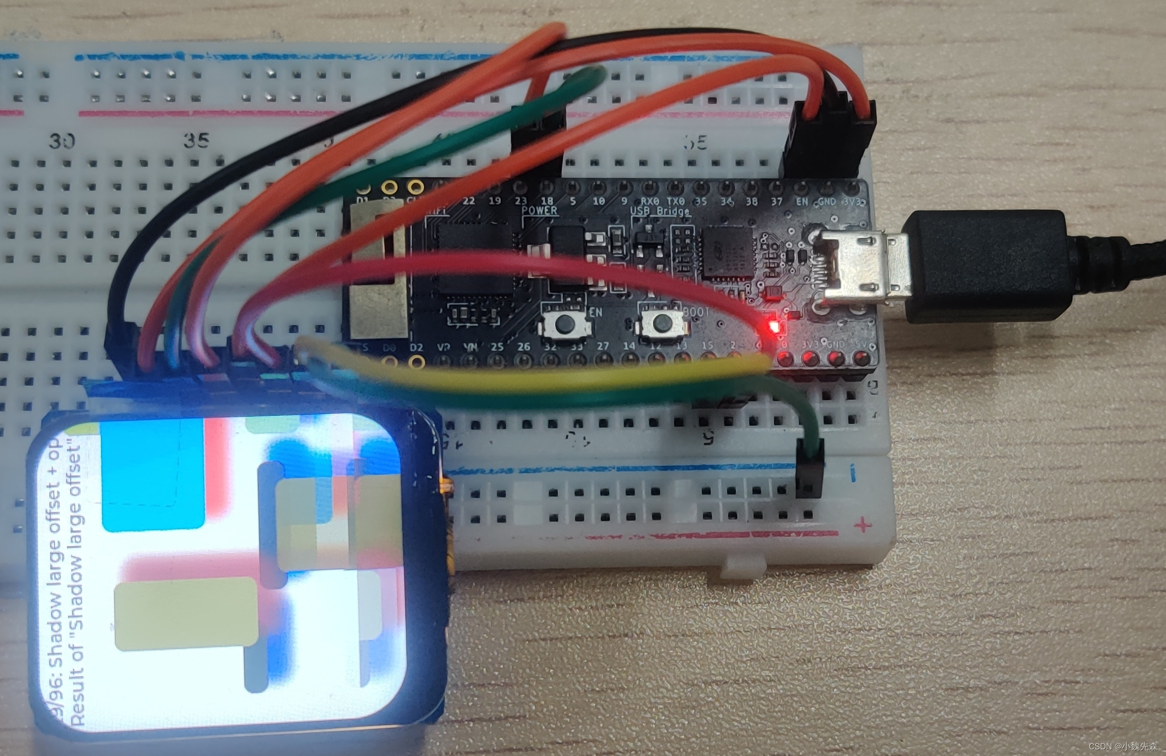
2、将第115行#if 0 改为#if 1,打开下面的示例注释,例如打开
lv_demo_benchmark(); (其它示例也是相同的操作步骤),此时编译会报错,
进入lv_demo_benchmark.c文件发现代码没有被使能,此时需要进入
lv_conf.h文件中将第736行改为
#define LV_USE_DEMO_BENCHMARK 1,此时
lv_demo_benchmark.c文件中的代码才会被使能。编译下载运行结果如下图所示。
四、编写自己的UI界面
开发工具:点击这里
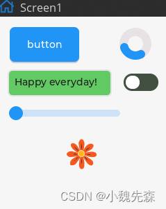
不同的版本操作基本一致,新建项目时需要填写屏幕大小和色深(16bit)。
随后随便点击几个控件,拖拽来摆放。如下图所示。
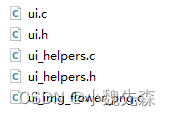
然后点击Explort File,生成界面代码。如下图所示。将这几个文件中所有的
#include "lvgl/lvgl.h"全部改为
#include "lvgl.h"
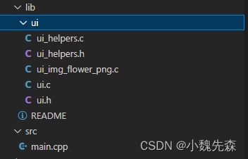
将上述几个文件放在一个文件夹中,并将该文件夹放在libs文件夹下,结构如图所示。
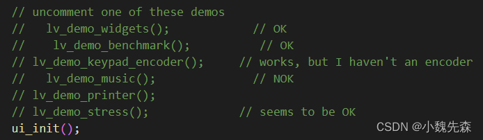
在main.cpp中添加头文件
#include<ui.h>,在下图所示位置添加
ui_init()
运行结果如下图所示
五、结语
lvgl的简单使用到此就结束了,有兴趣的还可以接着搞文件系统,中文显示等;然后结合Esp32的强大功能实现自己的小玩意。
大家有什么问题的话,欢迎提出问题。此外TFT_eSPI也支持了电子墨水屏的驱动,有兴趣的可以搞一搞。
版权归原作者 小魏先森 所有, 如有侵权,请联系我们删除。