1 前言
1.1 文档简介
介绍 VIN(video input)驱动配置,API 接口和上层使用方法。
1.2 目标读者
camera 驱动开发、维护人员和应用开发人员。
1.3 适用范围
表 1-1: 适用产品列表
内核版本驱动文件Linux-4.9drivers/media/platform/sunxi_vin/.cLinux-5.4drivers/media/platform/sunxi_vin/.c
2 模块介绍
2.1 模块功能介绍
- Video input 主要由接口部分(CSI/MIPI)和图像处理单元(ISP/VIPP)组成;
- CSI/MIPI 部分主要实现视频数据的捕捉;
- ISP 实现 sensor raw data 数据的处理,包括 lens 补偿、去坏点、gain、gamma、de-mosaic、de-noise、color matrix 等以及一些 3A 的统计;
- VIPP 能对将图进行缩小、和打水印处理。VIPP 支持 bayer raw data 经过 ISP 处理后再缩小,也支持对一般的 YUV 格式的 sensor 图像直接缩小。
2.2 相关术语介绍
表 2-1: 软件术语
相关术语解释说明ISPImage Signal Processor 图像信号处理VIPPVideo Input Post Processor 图像输入后处理MIPIMobile Industry Processor Interface 移动工业处理接口CCICamera Control Interface 摄像头控制接口TDMTime division multiplexing ISP 时分复用MCLKMaster clock(From AP to camera)摄像头主时钟PCLKPixel clock(From camera to AP,Sampling clock for data-bus)像素时钟YUVColor Presentation(Y for luminance,U&V for Chrominance)图像数据格式
2.3 驱动框架介绍
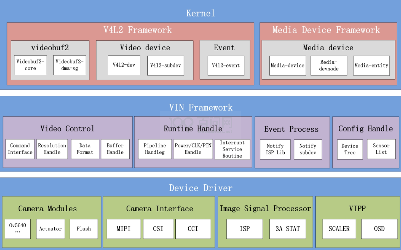
图 2-1: 驱动框图
VIN 驱动可以分为 Kernel 层、Video Input Framework、Device Driver 层。
2.3.1 Kernel 层
V4l2 Framework;
Linux 内核视频驱动第二版(Video for Linux Two );
适用于收音机、视频编解码、视频捕获以及视频输出设备驱动;
提供/dev/videoX 节点,应用通过该节点进行相应视频流和控制操作;
Media Device Framework;
Linux 多媒体设备框架;
适用于管理设备拓扑结构;
提供/dev/mediaX 节点,通过该节点应用可以获取媒体设备拓扑结构,并能够通过 API 控制子设备间数据流向。
2.3.2 Video Input Framework 层
- Video Control : 视频命令处理(分辨率协商,数据格式处理,Buffer 管理等);
- Runtime Handle : 运行时管理(Pipeline 管理,系统资源管理,中断调度等);
- Event Process : 事件管理(如上层调用,中断等事件的接收与分发);
- Config Handle : 配置管理(如硬件拓扑结构,模组自适应列表等)。
2.3.3 Device Driver 层
- Camera Modules : 模组驱动(图像传感器,对焦电机,闪光灯等驱动);
- Camera Interfac : 接口驱动(MIPI、Sub-Lvds 、HiSpi、Bt656、Bt601、Bt1120、DC等);
- Image Signal Processor : 图像处理器驱动(基本处理模块驱动,3A 统计驱动);
- Video Input Post Processor : 视频输入后处理(Scaler,OSD 等)。
2.4 模块配置介绍
2.4.1 kernel menuconfig 配置
- 首先,进入 Device Drivers,选择 Multimedia support ,然后依次打开 Cameras/video grabbers support 、Media Controller support 和 SUNXI platform devices, 如下图所示。
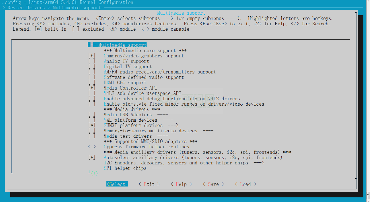 图 2-2: Device Drivers 选项配置
 - 其次,进入 SUNXI platform devices,选择 sunxi video input (camera csi/mipi isp vipp)driver 和 v4l2 new driver for SUNXI,如下图所示。
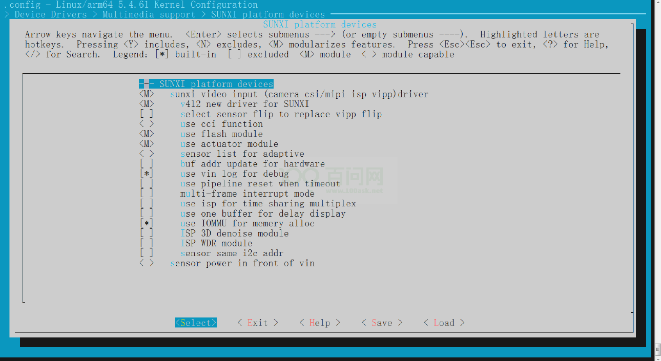 图 2-3: Device Drivers 选项配置
 - 最后,sunxi video input (camera csi/mipi isp vipp)driver 目录下的其他选项需要根据实际产品需求进行开关,如:使用闪光灯、对焦马达、打开 vin log、使用 IOMMU 如下图所示。
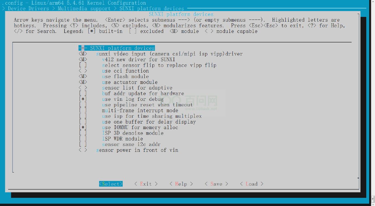 图 2-4: Device Drivers 选项配置
2.4.2 Device Tree 配置说明
• 设备树文件的配置是该 SoC 所有方案的通用配置,对于 ARM64 CPU 而言,设备树的路径为:kernel/{KERNEL_VERSION}/arch/arm64/boot/dts/sunxi/sun*.dtsi。
• 设备树文件的配置是该 SoC 所有方案的通用配置,对于 ARM32 CPU 而言,设备树的路径为:kernel/{KERNEL_VERSION}/arch/arm/boot/dts/sun*.dtsi。
• 板级设备树 (board.dts) 路径:
/device/config/chips/{IC}/configs/{BOARD}/KERNEL_VERSION/board.dts。
在 sun*.dtsi* 文件中,配置了该 SoC 的 CSI 控制器的通用配置信息,一般不建议修改,由 CSI 驱动维护者维护,如果需要修改配置请修改板级设备树 board.dts,板级设备树里面的内容会覆盖sun.dtsi 对应的信息。
• vind 配置
&vind0 {
vind0_clk = <336000000>;
vind0_isp = <300000000>;
status = "okay";
tdm0:tdm@0 {
work_mode = <0>;
};
isp00:isp@0 {
work_mode = <0>;
};
scaler00:scaler@0 {
work_mode = <0>;
};
scaler10:scaler@4 {
work_mode = <0>;
};
scaler20:scaler@8 {
work_mode = <0>;
};
scaler30:scaler@12 {
work_mode = <0>;
};
actuator0:actuator@0 {
device_type = "actuator0";
actuator0_name = "ad5820_act";
actuator0_slave = <0x18>;
actuator0_af_pwdn = <>;
actuator0_afvdd = "afvcc-csi";
actuator0_afvdd_vol = <2800000>;
status = "disabled";
};
flash0:flash@0 {
device_type = "flash0";
flash0_type = <2>;
flash0_en = <>;
flash0_mode = <>;
flash0_flvdd = "";
flash0_flvdd_vol = <>;
status = "disabled";
};
sensor0:sensor@0 {
device_type = "sensor0";
sensor0_mname = "gc2053_mipi";
sensor0_twi_cci_id = <1>;
sensor0_twi_addr = <0x6e>;
sensor0_mclk_id = <0>;
sensor0_pos = "rear";
sensor0_isp_used = <1>;
sensor0_fmt = <1>;
sensor0_stby_mode = <0>;
sensor0_vflip = <0>;
sensor0_hflip = <0>;
sensor0_iovdd-supply = <®_aldo2>;
sensor0_iovdd_vol = <1800000>;
sensor0_avdd-supply = <®_bldo2>;
sensor0_avdd_vol = <2800000>;
sensor0_dvdd-supply = <®_dldo2>;
sensor0_dvdd_vol = <1200000>;
sensor0_power_en = <>;
sensor0_reset = <&pio PA 18 1 0 1 0>;
sensor0_pwdn = <&pio PA 19 1 0 1 0>;
sensor0_sm_hs = <>;
sensor0_sm_vs = <>;
flash_handle = <&flash0>;
act_handle = <&actuator0>;
status = "okay";
};
sensor1:sensor@1 {
device_type = "sensor1";
sensor1_mname = "imx386_mipi_2";
sensor1_twi_cci_id = <0>;
sensor1_twi_addr = <0x20>;
sensor1_mclk_id = <1>;
sensor1_pos = "front";
sensor1_isp_used = <1>;
sensor1_fmt = <1>;
sensor1_stby_mode = <0>;
sensor1_vflip = <0>;
sensor1_hflip = <0>;
sensor1_iovdd-supply = <®_aldo2>;
sensor1_iovdd_vol = <1800000>;
sensor1_avdd-supply = <®_bldo2>;
sensor1_avdd_vol = <2800000>;
sensor1_dvdd-supply = <®_dldo2>;
sensor1_dvdd_vol = <1200000>;
sensor1_power_en = <>;
sensor1_reset = <&pio PA 20 1 0 1 0>;
sensor1_pwdn = <&pio PA 21 1 0 1 0>;
sensor1_sm_hs = <>;
sensor1_sm_vs = <>;
flash_handle = <>;
act_handle = <>;
status = "okay";
};
vinc00:vinc@0 {
vinc0_csi_sel = <0>;
vinc0_mipi_sel = <0>;
vinc0_isp_sel = <0>;
vinc0_isp_tx_ch = <0>;
vinc0_tdm_rx_sel = <0>;
vinc0_rear_sensor_sel = <0>;
vinc0_front_sensor_sel = <0>;
vinc0_sensor_list = <0>;
work_mode = <0x0>;
status = "okay";
};
vinc01:vinc@1 {
vinc1_csi_sel = <2>;
vinc1_mipi_sel = <0xff>;
vinc1_isp_sel = <1>;
vinc1_isp_tx_ch = <1>;
vinc1_tdm_rx_sel = <1>;
vinc1_rear_sensor_sel = <0>;
vinc1_front_sensor_sel = <0>;
vinc1_sensor_list = <0>;
status = "disabled";
};
vinc02:vinc@2 {
vinc2_csi_sel = <2>;
vinc2_mipi_sel = <0xff>;
vinc2_isp_sel = <2>;
vinc2_isp_tx_ch = <2>;
vinc2_tdm_rx_sel = <2>;
vinc2_rear_sensor_sel = <0>;
vinc2_front_sensor_sel = <0>;
vinc2_sensor_list = <0>;
status = "disabled";
};
vinc03:vinc@3 {
vinc3_csi_sel = <0>;
vinc3_mipi_sel = <0xff>;
vinc3_isp_sel = <0>;
vinc3_isp_tx_ch = <0>;
vinc3_tdm_rx_sel = <0>;
vinc3_rear_sensor_sel = <1>;
vinc3_front_sensor_sel = <1>;
vinc3_sensor_list = <0>;
status = "disabled";
};
…………
};
其中:
status 是 vin 驱动的总开关,对应的是 media 设备,使用 vin 时必须设为 okay;
vind0_clk 是 vin 模块的时钟,实际使用时可以根据 sensor 的帧率和分辨率来设置;
vind0_isp 是 isp 模块时钟,实际使用时可以根据 sensor 的帧率和分辨率来设置;
vind0_clk 表示 csi clk,计算公式:帧率 x (vts)x (hts)x 1(wdr 则为 2) / 8 / 1(双 pixel则为 2) / 1000000,向上取整,单位为 MH;vind0_isp 表示 isp clk,计算公式:帧率 x 宽 x 高 x 1.2 / 1000000,向上取整,单位为 MH;其中有些 ic 是没有 isp_clk,csi_clk 和isp_clk 都是设置在 vind0_clk。那么 vind0_clk 设置为 csi_clk 和 isp_clk 中最大的数值;
work_mode: 0:online mode 1:offline mode, 根据使用需求配置;
flash0_type: 0:FLASH_RELATING, 1:FLASH_EN_INDEPEND, 2:FLASH_POWER
flash0_en: flash enable gpio, type = 0 of 1
flash0_mode: flash mode gpio, type = 0 of 1
flash0_flvdd: flash module io power handle string, pmu power supply, type = 2
flash0_flvdd_vol: flash module io power voltage, pmu power supply, type = 2
status: 是否使用 flash, disable 代表关,okay 代表开
actuator0_name: vcm name
actuator0_slave: vcm iic slave address
actuator0_af_pwdn: vcm power down gpio
actuator0_afvdd: vcm power handle string, pmu power supply
actuator0_afvdd_vol: vcm power voltage, pmu power supply
status: vcm if used, disable 代表关,okay 代表开
device_type: sensor type sensor0_mname: sensor name
sensor0_twi_cci_id:sensor 所使用的 twi 或者 cci 的 id。
sensor0_twi_addr:sensor 的 twi 地址
sensor0_mclk_id:sensor 所使用的 mclk 的 id。
sensor0_pos:sensor 的位置,前置还是后置,主要用在平板上。
sensor0_isp_used: not use isp 1:use isp
sensor0_fmt: 0:yuv 1:bayer raw rgb
sensor0_stby_mode: not shut down power at standby 1:shut down power at standby
sensor0_vflip: flip in vertical direction 0:disable 1:enable
sensor0_hflip: flip in horizontal direction 0:disable 1:enable
sensor0_iovdd-supply: camera module io power handle string, pmu power supply
sensor0_iovdd_vol: camera module io power voltage, pmu power supply
sensor0_avdd-supply: camera module analog power handle string, pmu power supply
sensor0_avdd_vol: camera module analog power voltage, pmu power supply
sensor0_dvdd-supply: camera module core power handle string, pmu power supply
sensor0_dvdd_vol: camera module core power voltage, pmu power supply
sensor0_power_en: camera module power enable gpio
sensor0_reset: camera module reset gpio
sensor0_pwdn: camera module pwdn gpio sensor0_sm_hs: camera module sm_hs
gpio sensor0_sm_vs: camera module sm_vs gpio status: open or close sensor de
vice flash/actautor/sensor 节点用于对应的外设的开关和配置。这些节点的配置一般需要参
考对应方案的原理图和外设的 data sheet 来完成。
vinc0_csi_sel:表示该 pipeline 上 parser 的 id,必须配置,且为有效 id。
vinc0_mipi_sel:表示该 pipeline 上 mipi(sublvds/hispi)的 id,不使用时配置为 0xff。
vinc0_isp_sel:表示该 pipeline 上 isp 的 id,必须配置,当 isp 为空时,这个 isp 只是表示路由不做 isp 的效果处理。
vinc0_isp_tx_ch 表示该 pipeline 上 isp 的 ch,必须配置,默认为 0。当 sensor 是 bt656 多通道或者 WDR 出 RAW 时,该 ch 可以配置 0~3 的值。
vinc0_tdm_rx_sel: 表示该 pipeline 上 tdm rx 的 ch,必须配置,默认为 0。当不使用 tdm功能时,配置为 0xff;
vinc0_rear_sensor_sel 表示该 pipeline 上使用的后置 sensor 的 id。
vinc0_front_sensor_sel 表示该 pipeline 上使用的前置 sensor 的 id。
vinc0_sensor_list 表示是否使用 sensor_list 来时适配不同的模组,1 表示使用,0 表示不使用。
work_mode: 0:online mode 1:offline mode, 根据使用需求配置;只有 vinc0/4/8/12 可以配置。
status:vipp 的使能开关,okay or disable。
2.5 源码模块结构
驱动路径位于 drivers/media/platform/sunxi-vin 目录。
sunxi-vin:.
├── Kconfig
├── Makefile
├── modules
│   ├── actuator
│   │   ├── actuator.c     ;vcm driver的一般行为
│   │   ├── actuator.h     ;vcm driver的头文件
│   │   ├── ad5820_act.c   ;具体vcm driver型号实现
│   │   ├── an41908a_act.c ;具体vcm driver型号实现
│   │   ├── dw9714_act.c   ;具体vcm driver型号实现
│   │   ├── Makefile       ;编译文件
│   ├── flash
│   │   ├── flash.c ;led补光灯控制实现
│   │   ├── flash.h ;led补光灯驱动头文件
│   └── sensor
│   ├── ar0238.c      ;具体的sensor驱动
│   ├── camera_cfg.h  ;camera ioctl扩展命令头文件
│   ├── camera.h      ;camera公用结构体头文件
│   ├── gc030a_mipi.c ;具体的sensor驱动
│   ├── gc0310_mipi.c ;具体的sensor驱动
│   ├── gc5024_mipi.c ;具体的sensor驱动
│   ├── imx179_mipi.c ;具体的sensor驱动
│   ├── imx214.c      ;具体的sensor驱动
│   ├── imx219.c      ;具体的sensor驱动
│   ├── imx317_mipi.c ;具体的sensor驱动
│   ├── Makefile      ;驱动的编译文件
│   ├── nvp6134     ;具体的dvp sensor驱动
│   │   ├── acp.c
│   │   ├── acp_firmup.c
│   │   ├── acp_firmup.h
│   │   ├── acp.h
│   │   ├── common.h
│   │   ├── csi_dev_nvp6134.c
│   │   ├── csi_dev_nvp6134.h
│   │   ├── eq.c
│   │   ├── eq_common.c
│   │   ├── eq_common.h
│   │   ├── eq.h
│   │   ├── eq_recovery.c
│   │   ├── eq_recovery.h
│   │   ├── Makefile
│   │   ├── nvp6134c.c ;具体的sensor驱动实现
│   │   ├── type.h
│   │   ├── video.c
│   │   └── video.h
│   ├── nvp6158 ;具体的dvp sensor驱动
│   │   ├── audio.c ;音频部分实现
│   │   ├── audio.h ;音频部分头文件接口
│   │   ├── coax_protocol.c
│   │   ├── coax_protocol.h
│   │   ├── coax_table.h
│   │   ├── common.h
│   │   ├── Makefile
│   │   ├── modules.builtin
│   │   ├── modules.order
│   │   ├── motion.c
│   │   ├── motion.h
│   │   ├── nvp6158c.c ;具体的sensor驱动实现
│   │   ├── nvp6158_drv.c
│   │   ├── nvp6158_drv.h
│   │   ├── nvp6168_eq_table.h
│   │   ├── video_auto_detect.c
│   │   ├── video_auto_detect.h
│   │   ├── video.c
│   │   ├── video_eq.c
│   │   ├── video_eq.h
│   │   ├── video_eq_table.h
│   │   ├── video.h
│   ├── rn6854m_mipi.c ;具体的sensor驱动实现
│   ├── sensor-compat-ioctl32.c
│   ├── sensor_helper.c ;驱动函数接口的实现
│   ├── sensor_helper.h ;驱动函数接口的定义
├── modules.builtin
├── modules.order
├── platform
│   ├── platform_cfg.h ;vin平台配置文件
│   ├── sun50iw10p1_vin_cfg.h ;不同平台配置文件
│   ├── sun50iw3p1_vin_cfg.h ;不同平台配置文件
│   ├── sun50iw6p1_vin_cfg.h ;不同平台配置文件
│   ├── sun50iw9p1_vin_cfg.h ;不同平台配置文件
│   ├── sun8iw12p1_vin_cfg.h ;不同平台配置文件
│   ├── sun8iw15p1_vin_cfg.h ;不同平台配置文件
│   ├── sun8iw16p1_vin_cfg.h ;不同平台配置文件
│   └── sun8iw19p1_vin_cfg.h ;不同平台配置文件
├── top_reg.c
├── top_reg.h
├── top_reg_i.h
├── top_reg.o
├── utility
│   ├── bsp_common.c
│   ├── bsp_common.h
│   ├── bsp_common.o
│   ├── cfg_op.c ;读取ini文件的实现函数
│   ├── cfg_op.h ;读取ini文件的实现函数
│   ├── config.c ;sensor电压、通道选择、i2c地址等信息读取函数
│   ├── config.h ;sensor电压、通道选择、i2c地址等信息读取函数头文件
│   ├── vin_io.h ;vin模块寄存器操作头文件
│   ├── vin_os.c
│   ├── vin_os.h
│   ├── vin_supply.c
│   ├── vin_supply.h
├── vin.c
├── vin-cci
│   ├── bsp_cci.c ;底层cci bsp函数
│   ├── bsp_cci.h ;底层cci bsp函数头文件
│   ├── cci_helper.c ;cci 帮助函数,供sensor驱动调用
│   ├── cci_helper.h ;cci 帮助函数头文件
│   ├── csi_cci_reg.c ;cci硬件底层实现
│   ├── csi_cci_reg.h ;cci硬件底层实现头文件
│   ├── csi_cci_reg_i.h ;cci 寄存器资源头文件
│   ├── Kconfig
│   ├── sunxi_cci.c ;cci 平台驱动源文件
│   ├── sunxi_cci.h ;cci 平台驱动头文件
├── vin-csi
│   ├── parser_reg.c   ;CSI控制函数
│   ├── parser_reg.h   ;CSI控制函数头文件
│   ├── parser_reg_i.h ;CSI 寄存器值
│   ├── sunxi_csi.c    ;csi 子模块驱动原文件
│   ├── sunxi_csi.h    ;csi 子模块驱动头文件
├── vin.h
├── vin-isp
│   ├── isp500
│   │   ├── isp500_reg_cfg.c
│   │   ├── isp500_reg_cfg.h
│   │   ├── isp500_reg_cfg.o
│   │   └── isp500_reg.h
│   ├── isp520
│   │   ├── isp520_reg_cfg.c
│   │   ├── isp520_reg_cfg.h
│   │   └── isp520_reg.h
│   ├── isp521
│   │   ├── isp521_reg_cfg.c
│   │   ├── isp521_reg_cfg.h
│   │   └── isp521_reg.h
│   ├── isp522
│   │   ├── isp522_reg_cfg.c
│   │   ├── isp522_reg_cfg.h
│   │   └── isp522_reg.h
│   ├── isp_default_tbl.h
│   ├── sunxi_isp.c
│   ├── sunxi_isp.h
│   └── sunxi_isp.o
├── vin-mipi
│   ├── bsp_mipi_csi.c ;底层mipi bsp函数
│   ├── bsp_mipi_csi.h ;底层mipi bsp函数头文件
│   ├── bsp_mipi_csi_null.c ;底层mipi bsp空函数
│   ├── bsp_mipi_csi_v1.c   ;底层mipi bsp函数--v1
│   ├── combo_common.h
│   ├── combo_csi
│   │   ├── combo_csi_reg.c
│   │   ├── combo_csi_reg.h
│   │   └── combo_csi_reg_i.h
│   ├── combo_rx
│   │   ├── combo_rx_reg.c
│   │   ├── combo_rx_reg.h
│   │   ├── combo_rx_reg_i.h
│   │   └── combo_rx_reg_null.c
│   ├── dphy
│   │   ├── dphy.h ;mipi dphy头文件
│   │   ├── dphy_reg.c ;mipi dphy底层实现函数
│   │   ├── dphy_reg.h ;mipi dphy底层实现函数头文件
│   │   └── dphy_reg_i.h ;mipi dphy 寄存器资源头文件
│   ├── protocol
│   │   ├── protocol.h ;mipi协议层头文件
│   │   ├── protocol_reg.c ;mipi协议层底层实现
│   │   ├── protocol_reg.h ;mipi协议层底层实现头文件
│   │   └── protocol_reg_i.h
│   ├── protocol.h
│   ├── sunxi_mipi.c
│   ├── sunxi_mipi.h
├── vin-stat
│   ├── vin_h3a.c ;3A控制接口函数
│   ├── vin_h3a.h ;3A控制接口函数头文件
├── vin-tdm
│   ├── tdm_reg.c ;TDM寄存器控制函数
│   ├── tdm_reg.h
│   ├── tdm_reg_i.h
│   ├── vin_tdm.c
│   └── vin_tdm.h
├── vin_test
│   ├── mplane_image
│   │   ├── csi_test_mplane.c ;camera抓图测试用例
│   │   └── Makefile ;测试用例编译文件
│   ├── sunxi_camera_v2.h
│   └── sunxi_display2.h
├── vin-video
│   ├── dma_reg.c ;csi dma寄存器控制函数
│   ├── dma_reg.h ;csi dma寄存器控制函数
│   ├── dma_reg_i.h ;csi dma 寄存器值定义头文件
│   ├── vin_core.c ;vin模块核心
│   ├── vin_core.h ;vin模块核心头文件
│   ├── vin_video.c ; 数据格式处理、pipe通道选择、Buffer管理等函数
│   ├── vin_video.h ;数据格式处理、pipe通道选择、Buffer管理等函数头文件
└── vin-vipp
    ├── sunxi_scaler.c ;图像压缩处理函数
    ├── sunxi_scaler.h ;图像压缩处理函数头文件
    ├── vipp_reg.c ;vipp寄存器控制函数
    ├── vipp_reg.h ;vipp寄存器控制函数头文件
    ├── vipp_reg_i.h ;vipp寄存器具体描述头文件
3 V4L2 接口描述
3.1 VIDIOC_QUERYCAP
3.1.1 Parameters
Capability of csi driver(struct v4l2_capability * capability)
struct v4l2_capability {
    __u8 driver[16];    /* i.e. "bttv" */
    __u8 card[32];      /* i.e. "Hauppauge WinTV" */
    __u8 bus_info[32];  /* "PCI:" + pci_name(pci_dev) */
    __u32 version;      /* should use KERNEL_VERSION() */
    __u32 capabilities; /* Device capabilities */
    __u32 reserved[4];
};
3.1.2 Returns
Success:0; Fail: Failure Number
3.1.3 Description
获取驱动的名称、版本、支持的 capabilities 等,如 V4L2_CAP_STREAMIN,V4L2_BUF_TYPE_VIDEO_CAPTURE_MPLANE 等。
3.2 VIDIOC_ENUM_INPUT
3.2.1 Parameters
input(struct v4l2_input *inp)
struct v4l2_input {
    __u32 index;    /* Which input */
    __u8 name[32];  /* Label */
    __u32 type;     /* Type of input */
    __u32 audioset; /* Associated audios (bitfield) */
    __u32 tuner;    /* Associated tuner */
    v4l2_std_id std;
    __u32 status;
    __u32 capabilities;
    __u32 reserved[3];
};
3.2.2 Returns
Success:0; Fail: Failure Number
3.2.3 Description
获取驱动支持的 input index。目前驱动只支持 input index = 0 或 index = 1。
Index = 0 表示 primary csi device
Index = 1 表示 secondary csi device
应用输入 index 参数,驱动返回 type。对于 VIN 设备来说,type 为 V4L2_INPUT_TYPE_CAMERA。
3.3 VIDIOC_S_INPUT
3.3.1 Parameters
input(struct v4l2_input *inp)
The same as VIDIOC_ENUM_INPUT
3.3.2 Returns
Success:0; Fail: Failure Number
3.3.3 Description
通过 inp.index 设置当前要访问的 csi device 为 primary device 还是 secondary device。
Index = 0 (双摄像头配置中,一般对应后置摄像头。若只有一个摄像头设备,则 index 固定为0)
Index = 1(双摄像头配置中,一般对应前置摄像头)
调用该接口后,实际上会对 csi device 进行初始化工作。
在 A133 平台:Index 在 video0、1 时固定要设为 0;在 video2、3 要设为 1。
3.4 VIDIOC_G_INPUT
3.4.1 Parameters
input(struct v4l2_input *inp)
The same as VIDIOC_ENUM_INPUT
3.4.2 Returns
Success:0; Fail: Failure Number
3.4.3 Description
获取 inp.index,判断当前设置的 csi device 为 primary device 还是 secondary device。
Index = 0 (双摄像头配置中,一般对应后置摄像头。若只有一个摄像头设备,则 index 固定为0)
Index = 1(双摄像头配置中,一般对应前置摄像头)
3.5 VIDIOC_S_PARM
3.5.1 Parameters
Parameter(struct v4l2_streamparm *parms)
struct v4l2_streamparm {
    enum v4l2_buf_type type;
    union {
        struct v4l2_captureparm capture;
        struct v4l2_outputparm output;
        __u8 raw_data[200]; /* user-defined */
    } parm;
};
struct v4l2_captureparm {
    __u32 capability; /* Supported modes */
    __u32 capturemode; /* Current mode */
    struct v4l2_fract timeperframe; /* Time per frame in .1us units */
    __u32 extendedmode; /* Driver-specific extensions */
    __u32 readbuffers; /* # of buffers for read */
    __u32 reserved[4];
};
3.5.2 Returns
Success:0; Fail: Failure Number
3.5.3 Description
CSI 作为输入设备,只关注 parms.type 和 parms. capture。
应用使用时,parms.type = V4L2_BUF_TYPE_VIDEO_CAPTURE_MPLANE;
其中通过设定 parms->capture.capturemode(V4L2_MODE_VIDEO 或 V4L2_MODE_IMAGE),
实现视频或图片的采集。通过设定 parms->capture.timeperframe,可以设置帧率。
3.6 VIDIOC_G_PARM
3.6.1 Parameters
Parameter(struct v4l2_streamparm *parms)
The same as VIDIOC_S_PARM
3.6.2 Returns
Success:0; Fail: Failure Number
3.6.3 Description
应用使用时,parms.type = V4L2_BUF_TYPE_VIDEO_CAPTURE_MPLANE;
通过 parms->capture.capturemode 返回当前是 V4L2_MODE_VIDEO 或 V4L2_MODE_IMAGE;
通过 parms->capture.timeperframe, 返回当前设置的帧率。
3.7 VIDIOC_ENUM_FMT
3.7.1 Parameters
V4L2 format(struct v4l2_fmtdesc * fmtdesc)
struct v4l2_fmtdesc {
    __u32 index; /* Format number */
    enum v4l2_buf_type type; /* buffer type */
    __u32 flags;
    __u8 description[32]; /* Description string */
    __u32 pixelformat; /* Format fourcc */
    __u32 reserved[4];
};
3.7.2 Returns
Success:0; Fail: Failure Number
3.7.3 Description
获取驱动支持的 V4L2 格式。
应用输入 type,index 参数,驱动返回 pixelformat 。对于 VIN 设备来说,type 为V4L2_BUF_TYPE_VIDEO_CAPTURE_MPLANE。
3.8 VIDIOC_TRY_FMT
3.8.1 Parameters
Video type, format and size(struct v4l2_format * fmt)
struct v4l2_format {
    enum v4l2_buf_type type;
    union {
        struct v4l2_pix_format pix;
        struct v4l2_pix_format_mplane pix_mp;
        struct v4l2_window win;
        struct v4l2_vbi_format vbi;
        struct v4l2_sliced_vbi_format sliced;
        __u8 raw_data[200];
    } fmt;
};
struct v4l2_pix_format {
    __u32 width;
    __u32 height;
    __u32 pixelformat;
    enum v4l2_field field;
    __u32 bytesperline; /* for padding, zero if unused */
    __u32 sizeimage;
    enum v4l2_colorspace colorspace;
    __u32 priv; /* private data, depends on pixelformat */
};
3.8.2 Returns
Success:0; Fail: Failure Number
3.8.3 Description
根据捕捉视频的类型、格式和大小,判断模式、格式等是否被驱动支持。不会改变任何硬件设置。
对于 VIN 设备,type 为 V4L2_BUF_TYPE_VIDEO_CAPTURE_MPLANE。使用 struct v4l2_pix_format_mplane 进行参数传递。
应用程序输入 struct v4l2_pix_format_mplane 结构体里面的 width、height、pixelformat、field 等参数,驱动返回最接近的 width、height;若 pixelformat、field 不支持,则默认选择驱动支持的第一种格式。
3.9 VIDIOC_S_FMT
3.9.1 Parameters
Video type, format and size(struct v4l2_format * fmt)
The same as VIDIOC_TRY_FMT
3.9.2 Returns
Success:0; Fail: Failure Number
3.9.3 Description
设置捕捉视频的类型、格式和大小,设置之前会调用 VIDIOC_TRY_FMT。
对于 VIN 设备,type 为 V4L2_BUF_TYPE_VIDEO_CAPTURE_MPLANE。使用 struct v4l2_pix_format_mplane 进行参数传递。应用程序输入 width、height、pixelformat、field 等,驱动返回最接近的 width、height; 若 pixelformat、field 不支持,则默认选择驱动支持的第一种格式。
应用程序应该以驱动返回的 width、height、pixelformat、field 等作为后续使用传递的参数。对于 OSD 设备,type 为 V4L2_BUF_TYPE_VIDEO_OVERLAY。使用 struct v4l2_window进行参数传递。
应用程序输入水印的个数、窗口位置和大小、bitmap 地址、bitmap 格式以及 global_alpha 等。驱动保存这些参数,并在 VIDIOC_OVERLAY 命令传递使能命令时生效。
3.10 VIDIOC_G_FMT
3.10.1 Parameters
Video type, format and size(struct v4l2_format * fmt)
The same as VIDIOC_TRY_FMT
3.10.2 Returns
Success:0; Fail: Failure Number
3.10.3 Description
获取捕捉视频的 width、height、pixelformat、field、bytesperline、sizeimage 等参数。
3.11 VIDIOC_OVERLAY
3.11.1 Parameters
Overlay on/off(unsigned int i)
3.11.2 Returns
Success:0; Fail: Failure Number
3.11.3 Description
传递 1 表示使能,0 表示关闭。设置使能时会更新 osd 参数,使之生效。
3.12 VIDIOC_REQBUFS
3.12.1 Parameters
Buffer type ,count and memory map type(struct v4l2_requestbuffers * req)
struct v4l2_requestbuffers {
    __u32 count;
    enum v4l2_buf_type type;
    enum v4l2_memory memory;
    __u32 reserved[2];
};
3.12.2 Returns
Success:0; Fail: Failure Number
3.12.3 Description
v4l2_requestbuffers 结构中定义了缓存的数量,驱动会据此申请对应数量的视频缓存。多个缓存可以用于建立 FIFO,来提高视频采集的效率。这些 buffer 通过内核申请,申请后需要通过 mmap 方法,映射到 User 空间。
Count:定义需要申请的 video buffer 数量;
Type:对于 VIN 设备,为 V4L2_BUF_TYPE_VIDEO_CAPTURE_MPLANE;
Memory:目前支持 V4L2_MEMORY_MMAP、V4L2_MEMORY_USERPTR、V4L2_MEMORY_DMABUF 方式。
应用程序传递上述三个参数,驱动会根据 VIDIOC_S_FMT 设置的格式计算供需要 buffer 的大小,并返回 count 数量。
3.13 VIDIOC_QUERYBUF
3.13.1 Parameters
Buffer type ,index and memory map type(struct v4l2_buffer *buf)
struct v4l2_buffer {
    __u32 index;
    enum v4l2_buf_type type;
    __u32 bytesused;
    __u32 flags;
    enum v4l2_field field;
    struct timeval timestamp;
    struct v4l2_timecode timecode;
    __u32 sequence;

    /* memory location */
    enum v4l2_memory memory;
    union {
        __u32 offset;
        unsigned long userptr;
        struct v4l2_plane *planes;
    } m;
    __u32 length;
    __u32 input;
    __u32 reserved;
};
3.13.2 Returns
Success:0; Fail: Failure Number
3.13.3 Description
通过 struct v4l2_buffer 结构体的 index,访问对应序号的 buffer,获取到对应 buffer 的缓存信息。主要利用 length 信息及 m.offset 信息来完成 mmap 操作。
3.14 VIDIOC_DQBUF
3.14.1 Parameters
Buffer type ,index and memory map type(struct v4l2_buffer *buf)
struct v4l2_buffer is the same as VIDIOC_QUERYBUF
3.14.2 Returns
Success:0; Fail: Failure Number
3.14.3 Description
将 driver 已经填充好数据的 buffer 出列,供应用使用。
应用程序根据 index 来识别 buffer,此时 m.offset 表示 buffer 对应的物理地址。
3.15 VIDIOC_QBUF
3.15.1 Parameters
Buffer type ,index and memory map type(struct v4l2_buffer *buf)
3.15.2 Returns
Success:0; Fail: Failure Number
3.15.3 Description
将 User 空间已经处理过的 buffer,重新入队,移交给 driver,等待填充数据。
应用程序根据 index 来识别 buffer。
3.16 VIDIOC_STREAMON
3.16.1 Parameters
Buffer type(enum v4l2_buf_type *type)
3.16.2 Returns
Success:0; Fail: Failure Number
3.16.3 Description
此处的 buffer type 为 V4L2_BUF_TYPE_VIDEO_CAPTURE_MPLANE。运行此 IOCTL, 将 buffer 队列中所有 buffer 入队,并开启 CSIC DMA 硬件中断,每次中断便表示完成一帧 buffer 数据的填入。
3.17 VIDIOC_STREAMOFF
3.17.1 Parameters
Buffer type(enum v4l2_buf_type *type)
3.17.2 Returns
Success:0; Fail: Failure Number
3.17.3 Description
此处的 buffer type 为 V4L2_BUF_TYPE_VIDEO_CAPTURE_MPLANE。运行此 IOCTL,停止捕捉视频,将 frame buffer 队列清空,以及 video buffer 释放。
3.18 VIDIOC_QUERYCTRL
3.18.1 Parameters
Control id and value(struct v4l2_queryctrl *qc)
struct v4l2_queryctrl {
    __u32 id;
    enum v4l2_ctrl_type type;
    __u8 name[32]; /* Whatever */
    __s32 minimum; /* Note signedness */
    __s32 maximum;
    __s32 step;
    __s32 default_value;
    __u32 flags;
    __u32 reserved[2];
};
3.18.2 Returns
Success:0; Fail: Failure Number
3.18.3 Description
应用程序通过 id 参数,驱动返回需要调节参数的 name,minmum,maximum,default_value 以及步进 step。(由 v4l2 conctrols framework 完成)目前可能支持的 id 请参考 VIDIOC_S_CTRL。
3.19 VIDIOC_S_CTRL
3.19.1 Parameters
Control id and value(struct v4l2_queryctrl *qc)
The same as VIDIOC_QUERYCTRL
3.19.2 Returns
Success:0; Fail: Failure Number
3.19.3 Description
应用程序通过 id,value 等参数,对 camera 驱动对应的参数进行设置。
驱动内部会先调用 vidioc_queryctrl,判断 id 是否支持,value 是否在 minimum 和 maximum 之间。(由 v4l2 conctrols framework 完成)目前可能支持的 id 和 value 参考附件。
3.20 VIDIOC_G_CTRL
3.20.1 Parameters
Control id and value(struct v4l2_queryctrl *qc)
The same as VIDIOC_QUERYCTRL
3.20.2 Returns
Success:0; Fail: Failure Number
3.20.3 Description
应用程序通过 id,驱动返回对应 id 当前设置的 value。
3.21 VIDIOC_ENUM_FRAMESIZES
3.21.1 Parameters
index,type,format(struct v4l2_frmsizeenum)
enum v4l2_frmsizetypes {
    V4L2_FRMSIZE_TYPE_DISCRETE = 1,
    V4L2_FRMSIZE_TYPE_CONTINUOUS = 2,
    V4L2_FRMSIZE_TYPE_STEPWISE = 3,
};

struct v4l2_frmsize_discrete {
    __u32 width; /* Frame width [pixel] */
    __u32 height; /* Frame height [pixel] */
};

struct v4l2_frmsize_stepwise {
    __u32 min_width;   /* Minimum frame width [pixel] */
    __u32 max_width;   /* Maximum frame width [pixel] */
    __u32 step_width;  /* Frame width step size [pixel] */
    __u32 min_height;  /* Minimum frame height [pixel] */
    __u32 max_height;  /* Maximum frame height [pixel] */
    __u32 step_height; /* Frame height step size [pixel] */
};

struct v4l2_frmsizeenum {
    __u32 index;        /* Frame size number */
    __u32 pixel_format; /* Pixel format */
    __u32 type;         /* Frame size type the device supports. */
    union {             /* Frame size */
        struct v4l2_frmsize_discrete discrete;
        struct v4l2_frmsize_stepwise stepwise;
    };
    __u32 reserved[2]; /* Reserved space for future use */
};
3.21.2 Returns
Success:0; Fail: Failure Number
3.21.3 Description
根据应用传进来的 index,pixel_format,驱动返回 type,并根据 type 填写 discrete 或 step-wise 的值。Discrete 表示分辨率固定的值;stepwise 表示分辨率有最小值和最大值,并根据step 递增。上层根据返回的 type,做对应不同的操作。
3.22 VIDIOC_ENUM_FRAMEINTERVALS
3.22.1 Parameters
Index,format,size,type(struct v4l2_frmivalenum)
enum v4l2_frmivaltypes {
    V4L2_FRMIVAL_TYPE_DISCRETE = 1,
    V4L2_FRMIVAL_TYPE_CONTINUOUS = 2,
    V4L2_FRMIVAL_TYPE_STEPWISE = 3,
};
struct v4l2_frmival_stepwise {
    struct v4l2_fract min;  /* Minimum frame interval [s] */
    struct v4l2_fract max;  /* Maximum frame interval [s] */
    struct v4l2_fract step; /* Frame interval step size [s] */
};
struct v4l2_frmivalenum {
    __u32 index;        /* Frame format index */
    __u32 pixel_format; /* Pixel format */
    __u32 width;        /* Frame width */
    __u32 height;       /* Frame height */
    __u32 type;         /* Frame interval type the device supports. */
    union {             /* Frame interval */
        struct v4l2_fract discrete;
        struct v4l2_frmival_stepwise stepwise;
    };
    __u32 reserved[2]; /* Reserved space for future use */
};
3.22.2 Returns
Success:0; Fail: Failure Number
3.22.3 Description
应用程序通过 pixel_format、width、height、驱动返回 type,并根据 type 填写
V4L2_FRMIVAL_TYPE_DISCRETE、V4L2_FRMIVAL_TYPE_CONTINUOUS 或V4L2_FRMIVAL_TYPE_STEPWISE。Discrete 表示支持单一的帧率;stepwise 表示支持步进的帧率。
3.23 VIDIOC_ISP_EXIF_REQ
作用: 得到当前照片的 EXIF 信息,填写到相应的编码域中。目的:对于 raw sensor 尽量填写正规的 EXIF 信息,yuv sensor 该 IOCTRL 也可以使用,不过驱动中填写的也是固定值。相关参数:
struct v4l2_fract {
    __u32 numerator;
    __u32 denominator;
};

struct isp_exif_attribute {
    struct v4l2_fract exposure_time;
    struct v4l2_fract shutter_speed;
    __u32 aperture;
    __u32 focal_length;
    __s32 exposure_bias;
    __u32 iso_speed;
    __u32 flash_fire;
    __u32 brightness;
};

struct v4l2_fract exposure_time;
曝光时间:分数类型,例如numerator = 1,denominator = 200,则表示1/200秒的曝光时间。

struct v4l2_fract shutter_speed;
快门速度:分数类型,例如numerator = 1,denominator = 200,则表示1/200秒的快门速度。(实际上和曝光时间数值相同)

__u32 aperture;
光圈大小:FNumber,例如aperture = 22,则表示,光圈大小为2.2,即FNumber = 22/10;

__u32 focal_length;
焦距:例如focal_length = 1400,则表示焦距为14mm,即FocalLength = 1400/100( mm);

__s32 exposure_bias;
曝光补偿:范围 -4~4

__u32 iso_speed;
感光速度:50~3200

__u32 flash_fire;
闪光灯是否开启:flash_fire = 1 表示闪光灯开启,flash_fire = 0 表示闪光灯未开启。

__u32 brightness;
图像亮度:0~255.

使用示例:
int V4L2CameraDevice::getExifInfo(struct isp_exif_attribute *exif_attri)
{
    int ret = -1;
    if (mCameraFd == NULL)
    {
        return 0xFF000000;
    }
    ret = ioctl(mCameraFd, VIDIOC_ISP_EXIF_REQ, exif_attri);
    return ret;
}
4 模块使用范例
4.1 测试 demo
模块使用的 demo 的代码位于 drivers/media/platform/sunxi-vin/vin_test/mplane_image;此目录下可以直接 make 生成 demo;把 demo 推到机器里面执行便可以获取指定 video 节点的图像。推荐在 pc 上创建 bat 批处理文件,使用 adb 命令完成一系列抓图的动作,bat 内容参考如下,不同机器请注意修改 push 进去的路径:
del .\result\*.bin
adb root
adb remount
adb shell "mkdir /vendor/extsd/"
adb shell "mkdir /vendor/extsd/result"
adb shell rm /vendor/extsd/result/*.bin
adb push demo路径\csi_test_mplane /vendor/extsd/csi_test1
adb shell chmod 777 /vendor/extsd/csi_test1
adb shell "cd /vendor/extsd/ && ./csi_test1 0 0 1920 1080 ./result 1 20000 60 0"
adb shell ls /vendor/extsd/result
adb pull /vendor/extsd/result
pause
最后会在 bat 指令的文件夹生成 result 文件夹里面保存二进制的图像数据 *.bin 文件;可用 RawViewer 等软件查看图像数据。demo 参数说明:0 0 1920 1080 ./result 1 20000 60 0,分别表示 video0,set_input index0,目标分辨率宽,目标分辨率高,bin 文件保存路径、图像格式(如 NV21,具体含义可以看 demo 代码的 s_fmt 参数)、采集帧数(帧数大于 10000 即为常开节点)、目标帧率、和是否开启 wdr。
4.2 调用流程
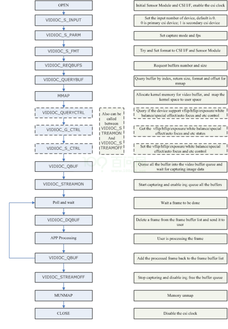
图 4-1: CSI 调用流程
5 FAQ
5.1 调试方法
5.1.1 调试节点
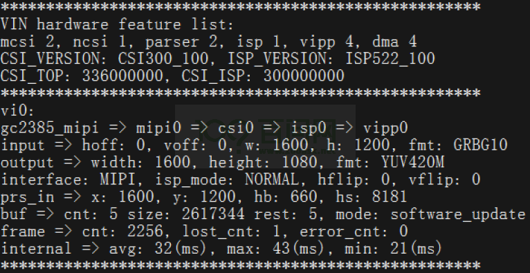
图 5-1: vi 节点
当系统打开 DEBUG_FS 编译宏时,可以 cat /sys/kernel/debug/mpp/vi 查看;否则可以
cat /sys/devices/platform/soc@2900000/2000800.vind/vi。
vi 节点保存的是当前或上一次工作(当前没有工作)的状态。下面对 vi 节点的关键信息进行说明。
CSI_TOP、CSI_ISP 分别是对应 CSI、和 ISP 的工作频率;input 一行表示 CSI 接收到的图片尺寸,fmt 表示输入数据的格式;
output 表示 CSI 出尺寸,如果使用了缩放或者裁剪,那么输入输出尺寸会不一致,fmt 表示数据的输出格式;
最后一行分别表示平均帧间隔、最大帧间隔、最小帧间隔,可以计算得出帧率,调试帧率时可以参考。
5.1.2 settle time
方式一:修改对应 sensor 驱动中的 sensor_probe 函数,可以添加或修改 info->time_hs 的值即可。

图 5-2: info->time_hs
方式二:通过 mipi 子设备的 settle_time 节点在线进行修改,settle_time 节点路径:/sys/devices/platform/soc/5800800.vind/5810100.mipi。
进入节点路径后,可以看到当前目录下存在 settle_time 节点:

图 5-3: settle time 节点
可以通过 cat、echo 命令,对 settle_time 节点进行读写操作:

图 5-4: settle time 节点读写
调整策略:settle time 的值慢慢增大调整,调大直到不能出图,再取一个略低于最大值的数值即可。调整范围:0x00-0xff。
5.1.3 信号状态
介绍如何观测 SOC 主控的接收数据的信号状态,分别对 MIPI 和并口做出说明。
5.1.3.1 MIPI
MIPI 传输模式有两种:
LP(Low-Power)模式:用于传输控制信号,最高速率 10 MHz。
HS(High-Speed)模式:用于高速传输数据,以 MIPI DPHY V1.1 版本为例,速率范围 [80Mbps - 1.5Gbps] per Lane。
可以通过查看 user manual MIPI PHY 部分寄存器,观测 SOC 识别到的 clock lane 和 data lane 的 LP、HS 状态。
5.1.3.2 并口
对于并口接口的 sensor,可以查看 user manual CSI PARSER 部分的 parser signal 寄存器,观测 sensor 端 PCLK、DATA 的信号状态。以此判断 parser 是否有识别到 sensor 端发送的数据。
5.2 常见问题
5.2.1 I2C 不通
如下图打印:

图 5-5: i2c 不通
【分析步骤一】:确认供电、MCLK、i2c 上拉等外围电路信号是否正常。使用万用表测量板子上AVDD、DVDD、IOVDD 供电电压、MCLK 频率、幅度、RESET、PWDN 的电平是否符合要求。
【分析步骤二】:确认 i2c 地址,TWI 通道是否和原理图一致。
【分析步骤三】:以上都正常就用示波器或者逻辑分析仪测量分析主控发出 i2c 波形是否正确、有无回应;最后可以考虑 sensor 损坏或者接口错位等问题。
5.2.2 sensor 不出图
【分析步骤一】:确认 chip id 和 datasheet 上一致。
在对应 sensor 驱动的 sensor_detect 函数中读 chip id 寄存器,这一步也能检验 i2c 的读写是否正确。
【分析步骤二】:确认配置已经配置到 sensor 里。
可以把写进去的寄存器读出来和写入值对比是否一致。
【分析步骤三】:确认配置正确并且 sensor 已经输出图像。
和原厂确认寄存器配置、用示波器测量 sensor 端的 mipi 数据 lane 和时钟 lane 波形,分析是否正在发送数据。
【分析步骤四】:确认 SOC 是否接收到 sensor 数据。
- mipi 的 clock lane 存在两种工作模式,一种是连续时钟模式,传输过程不会切换 LP 状态;另一种是非连续时钟信号模式,每传输完一帧图像数据,帧 blanking 时将会切换为 LP 状态。目前大部分 MIPI sensor 一般都是非连续时钟模式。
- 如果 sensor 是连续时钟模式,要保证 MIPI 在 sensor 之前初始化,需要在 sensor 驱动 sensor_probe() 中配置 info->stream_seq = MIPI_BEFORE_SENSOR;
- 如果 sensor 是非连续时钟模式,可以通过判断 SOC 识别到的 LP、HS 模式状态是否在不断切换,来间接判断 SOC 的 MIPI 的接收状态。
- 查看 user manual MIPI PHY 部分寄存器,观测 clock lane 和 data lane 的 LP、HS 状态是否有在不断切换,有则说明 MIPI 已经接收到了 sensor 发送的数据。如果没有切换则说明 MIPI 没有正确接收 sensor 数据。此时应该检查 MIPI 相关配置是否正确。
【分析步骤五】:尝试修改 settle time。
如果可以确定 sensor 已经在正确发送数据,只是 MIPI 这边一直接收不到导致无法出图,可以尝试修改 settle time(参考调试方法章节)。
5.2.3 已出图但画面是绿色或者粉红色
一般是 YUYV 顺序反了,可以修改 sensor 驱动中 sensor_formats 结构体的 mbus_code 参数,修改 YUV 顺序即可。
5.2.4 I2c 已通,但是读所有 sensor 寄存器值都为 0
【分析步骤一】检查 i2c 通讯 addr 和 data 的位宽。
检查 sensor 驱动中 cci_drv 结构体中定义的值是否符合 datasheet 要求。
【分析步骤二】检查 i2c 通讯数据大小端是否不一致。
可以在读 sensor id 时把地址高低位相反来快速验证一下。
5.2.5 画面旋转 180 度
可以修改 board.dts 里面的 hflip 和 vflip 来解决,如果画面和人眼成 90 度的话,只能通过修改 sensor 配置来解决(只有部分 sensor 支持)。
5.2.6 没有 video 节点
【问题解析】没有加载 ko 或者 ko 加载失败。
【分析步骤一】检查模块加载顺序是否正确。
lsmod 看一下模块是否加载正确,如果报的错误是 [VIN_ERR]registering gc2355_mipi, No such device! 则表明 sensor 模块 gc2355_mipi 没有加载。
【分析步骤二】检查 board.dts 文件配置是否配置了 vind0,且 status 为 okay。
【分析步骤三】如果是加载失败检查加载失败的原始是 i2c 不通还是没有 ko。
i2c 不通参考前面的分析,没有 ko 请检查是否有对应的驱动并且在 Makefile 中使能了编译。
版权归原作者 韦东山 所有, 如有侵权,请联系我们删除。